
PTZ scanning path generation method based on graphic perception

A scanning path and graphics technology, applied in image communication, color TV components, TV system components, etc., can solve the problem of low PTZ scanning path efficiency, and achieve the effect of improving installation and deployment efficiency and reducing workload.

Active Publication Date: 2020-06-05
CHENGDU YINENG SCI&TECH CO LTD
View PDF16 Cites 0 Cited by
  • Summary
  • Abstract
  • Description
  • Claims
  • Application Information

AI Technical Summary

Problems solved by technology

[0005] The present invention aims to solve the problem of low efficiency in the existing way of setting PTZ scanning paths, and proposes a method for generating PTZ scanning paths based on graphic perception

Method used


Image

  • PTZ scanning path generation method based on graphic perception
  • PTZ scanning path generation method based on graphic perception
  • PTZ scanning path generation method based on graphic perception

Examples


Embodiment

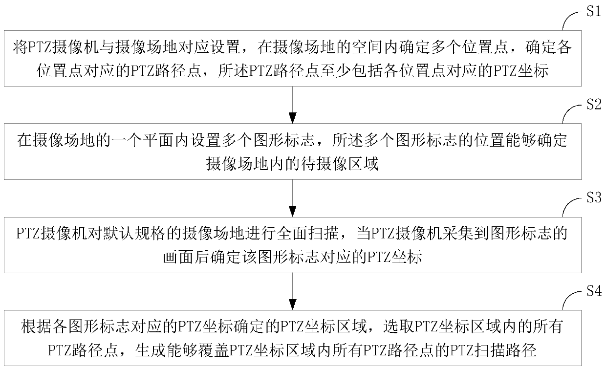
[0043] The method for generating a PTZ scan path based on graphic perception described in the embodiment of the present invention, such as figure 1 shown, including the following steps:

[0044] Step S1. The PTZ camera is set correspondingly to the shooting site, and a plurality of position points are determined in the space of the shooting site, at least a part of the plurality of position points is in the area to be photographed, and the PTZ path points corresponding to each position point are determined, so The PTZ waypoints at least include PTZ coordinates corresponding to each location point;

[0045] Wherein, the shooting site can be a classroom, and the area to be captured can be the seating area of ​​the students, and the PTZ camera can be installed in a horizontal center and vertically upper position on the front wall of the classroom, for example, it is set on the horizontal center of the front wall of the classroom and 1.8-3 meters away from the ground, facing the ...


PUM


Abstract

The invention relates to the technical field of PTZ. The invention aims t solving a problem of low efficiency of setting a PTZ scanning path in the existing manual mode and provides a PTZ scanning path generation method based on graphic perception. The method comprises the following steps that: multiple position points are determined in space of a camera shooting site, PTZ path points corresponding to the position points are determined, and the PTZ path points at least comprise PTZ coordinates corresponding to the position points; a plurality of graphic marks are arranged in one plane of the camera shooting site, and the positions of the graphic marks can determine a to-be-shot area in the camera shooting site; a PTZ camera carries out comprehensive scanning on the camera shooting site, and PTZ coordinates corresponding to the graphic marks are determined; and a PTZ coordinate area is determined according to the PTZ coordinate corresponding to each graphic mark, and a PTZ scanning pathcapable of covering all PTZ path points in the PTZ coordinate area is generated. The PTZ scanning path is automatically generated, the installation and deployment efficiency is improved, and the method is suitable for classrooms.

Description

technical field [0001] The invention relates to the technical field of PTZ, in particular to a method for generating a PTZ scanning path. Background technique [0002] PTZ, namely Pan (translation), Tilt (tilt), and Zoom (zoom), refers to a camera that supports omnidirectional (horizontal, vertical) movement and lens zoom and zoom control. The PTZ camera has two built-in motors in the horizontal direction and the vertical direction. The angles of the two motors are different, so that the PTZ camera faces different angles. [0003] It is a new type of application to deploy a camera in a venue such as a classroom, use the camera to obtain video images in the venue, and scan and recognize faces from the images. When the size of the venue is large, ordinary cameras cannot display images of all personnel on the screen, and PTZ cameras can be used instead. The PTZ camera changes the shooting angle and magnification through the movement of the internal motor, so that it can clear...

Claims


Application Information

Patent Timeline
Patent Type & Authority Applications(China)
IPC IPC(8): H04N5/232
CPCH04N23/671H04N23/67
Inventor 罗章璞
Owner CHENGDU YINENG SCI&TECH CO LTD
Learn More