
MIMO sonar distance sidelobe suppression method based on deconvolution

A distance sidelobe and deconvolution technology, which is applied in the directions of sound wave reradiation, instruments, and measuring devices, can solve problems such as excessive calculation and poor waveform robustness

Active Publication Date: 2020-06-09
NORTHWESTERN POLYTECHNICAL UNIV
View PDF0 Cites 0 Cited by
  • Summary
  • Abstract
  • Description
  • Claims
  • Application Information

AI Technical Summary

Problems solved by technology

However, due to the non-perfect orthogonality between the transmitted waveforms used and the waveform distortion caused by the underwater acoustic channel, there are high range-dimensional sidelobe interferences in the output of MIMO sonar imaging results (Liu Xionghou, Sun Chao, Zhuo Jie, etc. Mismatch filtering processing of MIMO imaging sonar based on convex optimization method. Journal of Northwestern Polytechnical University, 2013; 31(3):367-372)
Although the use of longer coding sequences can suppress the sidelobe of the distance dimension to a certain extent, it is easy to cause problems such as excessive calculation and poor waveform robustness.
How to effectively suppress the sidelobe of the distance dimension without increasing the length of the coding sequence, the existing research cannot solve this problem

Method used


Image

  • MIMO sonar distance sidelobe suppression method based on deconvolution
  • MIMO sonar distance sidelobe suppression method based on deconvolution
  • MIMO sonar distance sidelobe suppression method based on deconvolution

Examples


Embodiment Construction

[0058] see figure 1 - Fig. 7, main content of the present invention has:

[0059] 1. Design the corresponding point spread function (PSF: point spread function) for the orthogonal waveform used by MIMO sonar

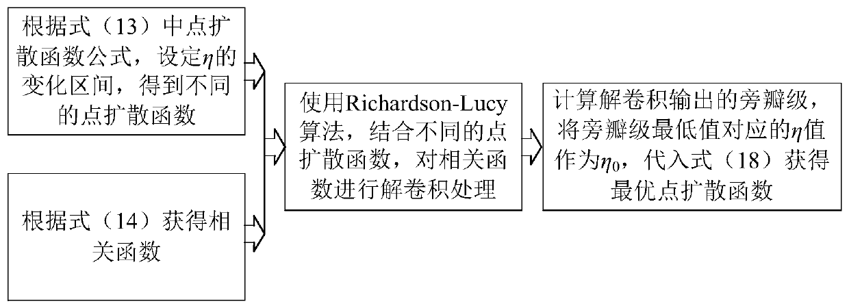
[0060] 2. Design the MIMO sonar range sidelobe suppression process based on deconvolution. The process uses the designed PSF and Richardson-Lucy algorithm to deconvolute the absolute value of each beam output in the MIMO sonar imaging results to obtain the imaging results after range sidelobe suppression

[0061] 3. MIMO sonar imaging results and the side lobe suppression method results proposed by the present invention are provided by computer numerical simulation, and the angle of distance side lobe level is illustrated from the imaging results of single scattering point targets and multi-scattering point targets, Compared with existing MIMO sonar imaging methods, the proposed sidelobe suppression method has lower distance sidelobes.

[0062] Technical scheme of the...


PUM


Abstract

The invention relates to an MIMO sonar distance sidelobe suppression method based on deconvolution. According to the method, an optimal point spread function is designed according to orthogonal waveforms used by the MIMO sonar, and deconvolution processing is performed on a beam output absolute value by using the optimal point spread function and a Richardson-Lucy algorithm so that distance sidelobes in the MIMO sonar imaging result can be effectively suppressed. Compared with a traditional MIMO sonar imaging method, the MIMO sonar distance sidelobe suppression method based on deconvolution can significantly reduce the distance sidelobe in imaging output.

Description

technical field [0001] The invention belongs to the field of sonar imaging, in particular to a deconvolution-based MIMO sonar range sidelobe suppression method. Background technique [0002] In the field of underwater acoustic imaging, multiple-input multiple-output (MIMO: multiple-input multiple-output) sonars can obtain better angular resolution than traditional single-input multiple-output (SIMO: single-input multiple-output) sonars (Liu XH, Sun C, Zhuo J, and et al, "Devising MIMO arrays for underwater 3-Dshort-range imaging," in Proc MTS / IEEE OCEANS'12, Hampton Roads, USA, pp.1-7, Oct.2012. Sun C, Liu X H, Zhuo J, and et al, "High-Resolution 2-D Sector-ScanImaging Using MIMO Sonar with Narrowband LFM pulses," in Proc OCEANS'13MTS / IEEE, San Diego, USA, Sep.2013.) . However, due to the non-perfect orthogonality between the transmitted waveforms used and the waveform distortion caused by the underwater acoustic channel, there are high range-dimensional sidelobe interfere...

Claims


Application Information

Patent Timeline
IPC IPC(8): G01S15/89G01S7/53G01S7/527G01S7/52
CPCG01S15/89G01S7/53G01S7/5273G01S7/52003
Inventor 刘雄厚孙超魏焘杨益新卓颉
Owner NORTHWESTERN POLYTECHNICAL UNIV
Learn More