Method for designing millimeter wave radar signal waveform

A millimeter-wave radar and signal waveform technology, applied in the field of radar communication, can solve problems such as complex road conditions or military environments, and non-correlated side lobes limit wider application, and achieve the effect of eliminating interference and suppressing distance side lobes

Inactive Publication Date: 2013-05-08
BEIJING INSTITUTE OF TECHNOLOGYGY +1
View PDF1 Cites 0 Cited by
  • Summary
  • Abstract
  • Description
  • Claims
  • Application Information

AI Technical Summary

Problems solved by technology

Although the above-mentioned method of distinguishing multiple targets is adopted, the road conditions or military environment are very complicated, and there are certain problems in the adaptability of the SFMCW signal system when there are many targets within the radar antenna beam range
[0006] Pseudo-noise coded continuous wave radar has received more research in other fields in recent years. The commonly used m-sequence pseudo-random coded phase-modulated continuous wave system has strong anti-interference ability, and the pin-shaped fuzzy map can achieve high-precision distance measurement and speed measurement. capability, however the presence of uncorrelated sidelobes limits the broader application of this regime

Method used


Image

  • Method for designing millimeter wave radar signal waveform
  • Method for designing millimeter wave radar signal waveform
  • Method for designing millimeter wave radar signal waveform

Examples


Embodiment 1

[0027] A method for designing a millimeter-wave radar signal waveform, the specific process of which is:

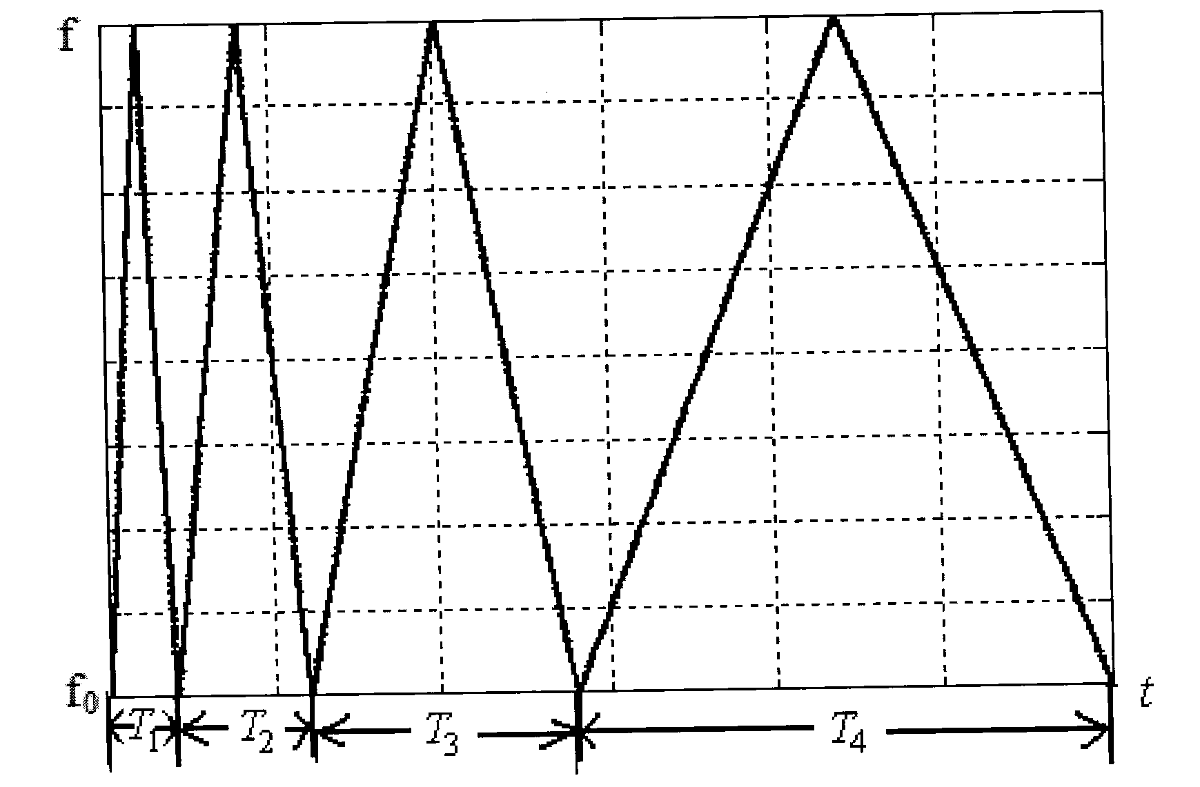
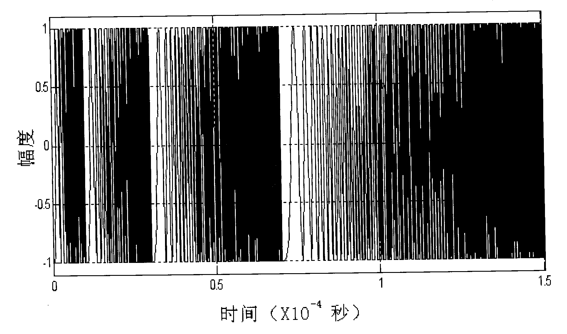
[0028] 1) The signal processing module of the automotive anti-collision radar system generates a pseudo-random code sequence PN(t), and uses this pseudo-random code to modulate such as figure 1 The variable-period FM signal shown in the figure can be used to obtain the radar emission waveform within one bit of the pseudo-random code sequence, which can be expressed as:

[0029] s ( t ) = PN ( t ) Σ n = 1 4 rect ( t - n T n T n ) ...

Embodiment 2

[0048] A design method of millimeter-wave radar signal waveform, using variable-period FMCW waveform has good advantages in multi-target recognition, and can solve the problem of false targets existing in traditional linear frequency modulation continuous wave radar.

[0049] Assuming that there are 4 targets in front of the car, the echo signal is the superposition of the echo signals of these 4 points, and the beat signal can also be approximately considered as the sum of the beat signals of the echo signals of each point target and the transmitted signal.

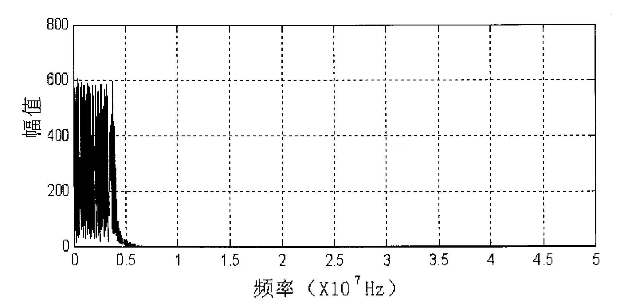
[0050] Perform spectrum analysis on the beat signal in the frequency rising section to obtain 4 spectral peaks, which are denoted as f a1 , f a2 , f a3 , f a4 , in the same way, the spectrum analysis of the beat signal in the frequency drop section can obtain another 4 spectral peaks, which are respectively denoted as f b1 , f b2 , f b3 , f b4 . Since the corresponding relationship between the spectral lines in th...


PUM


Abstract

The invention relates to a method for designing a millimeter wave radar signal waveform, in particular to a method for designing the radar signal waveform under the condition of multi-target recognition in a complicated road or a military environment, and belongs to the technical field of radar communication. In the invention, a mode of combining a linear frequency modulation continuous wave radar system and a pseudo-random code continuous wave radar system is adopted, and a period variation mode during design of an automobile anti-collision radar emission signal waveform is adopted at the same time. In the method, effective detection for large-distance targets is realized by using relevant good characteristics of a pseudo-random code; a distance sidelobe can be effectively restrained by adopting the mode of combining the linear frequency modulation and the pseudo-random code; the flexible period variation mode is adopted during the design of the automobile anti-collision radar emission signal waveform, so multi-target detection in the complicated environment can be facilitated; due to pseudo-random code phase modulation, different codes on different vehicle-mounted radars can be realized; therefore, interferences caused by radars of coming vehicles can be eliminated.

Description

technical field [0001] The invention relates to a design method of a millimeter-wave radar signal waveform, in particular to a design method of a radar signal waveform under the condition of multi-target identification in complex roads or military environments, and belongs to the technical field of radar communication. Background technique [0002] In the environment where automobile active anti-collision systems and military multi-targets exist, radars face multi-target situations in most cases. In addition to relying on antenna beams to distinguish targets in different directions, multi-targets in the same direction can only rely on Therefore, the selection of the ranging signal system of the millimeter wave radar must be able to meet the basic requirements of multi-target detection. [0003] At present, the ranging signal schemes researched and applied in anti-collision radar mainly include pulse scheme, FSK scheme, SFCW scheme, LFMCW scheme and pseudo-random coding schem...

Claims


Application Information

Patent Timeline
Patent Type & Authority Patents(China)
IPC IPC(8): G01S7/36
Inventor 卢继华陈奎熹卜祥元安建平李安培张军郑晨
Owner BEIJING INSTITUTE OF TECHNOLOGYGY
Why Eureka
Try Eureka