
A mimo radar sidelobe suppression method

A sidelobe suppression and radar technology, applied to radio wave measurement systems, instruments, etc., can solve the problems of reduced resolution, reduced output signal in-band ripple, and loss of signal-to-noise ratio to reduce complexity and computation , Suppress the distance side lobe, avoid the effect of fluctuation

Active Publication Date: 2021-08-31
SHANGHAI RADIO EQUIP RES INST
View PDF5 Cites 0 Cited by
  • Summary
  • Abstract
  • Description
  • Claims
  • Application Information

AI Technical Summary

Problems solved by technology

[0004] Matched filter windowing method can well suppress the sidelobe of large time-band product signals, but at the cost of loss of signal-to-noise ratio and reduced resolution, and the effect of windowing on small band-product signals is not good
The sub-band reciprocal spectral filtering method performs spectral correction on the sub-band signal, which cannot effectively eliminate the mutual influence between the quadrature echo signals and reduce the in-band ripple of the output signal.
The comprehensive signal spectrum correction processing method corrects the spectrum of the composite signal, replacing the two links of matched filtering and equivalent transmit beamforming in the conventional processing, and eliminates the mutual influence between the orthogonal echo signals for the composite bandwidth spectrum correction, reducing the The in-band ripple of the output signal is reduced, but the bandwidth of the output signal of this method is the synthesis bandwidth, which cannot be down-sampled subsequently, which increases the complexity of the system. At the same time, there are three types of range ambiguity sidelobe and Doppler sensitivity problems.

Method used


Image

  • A mimo radar sidelobe suppression method
  • A mimo radar sidelobe suppression method
  • A mimo radar sidelobe suppression method

Examples


Embodiment Construction

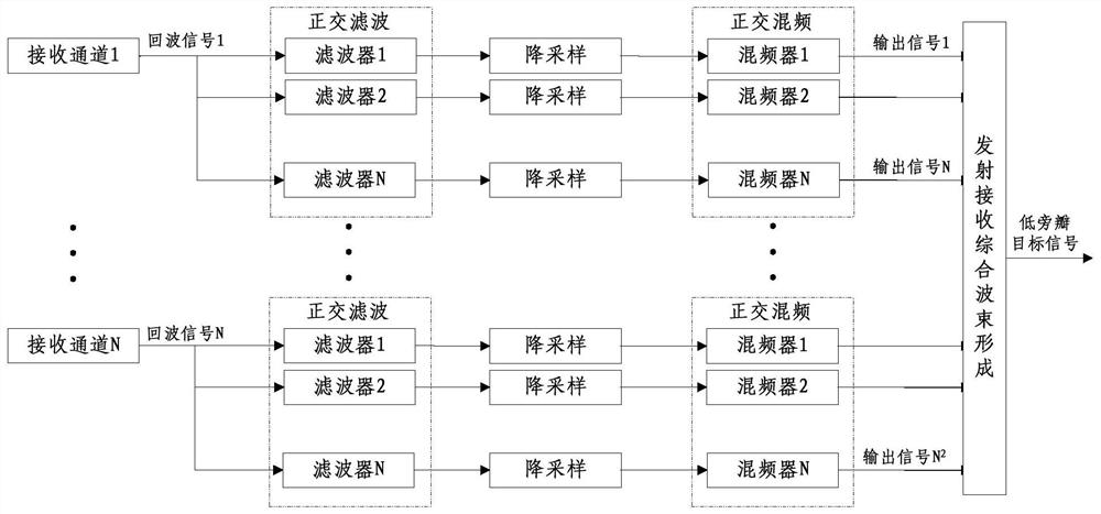
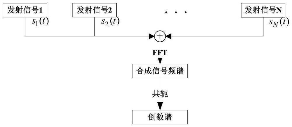
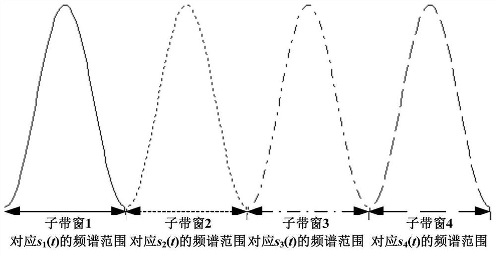
[0029] based on the following Figure 1 ~ Figure 4 , specifically explain the preferred embodiment of the present invention.

[0030] Such as figure 1 As shown, the present invention provides a MIMO radar sidelobe suppression method, comprising the following steps:

[0031] Step S1. Obtain N orthogonal filters according to the composite reciprocal spectrum of the transmitted signals of N channels and N orthogonal subband windows;

[0032] Step S2, performing channel separation on the echo signals of N channels in sequence. The channel separation includes three steps: orthogonal filtering, down-sampling and quadrature mixing. The echo signals of N channels are separated to obtain N 2 road signal;

[0033] Step S3, N after channel separation 2 The received signals are weighted and accumulated to complete the combined transmission and reception beamforming to obtain low sidelobe target signals.

[0034] Such as figure 2 As shown, the solution method of the synthetic recipr...


PUM


Abstract

A sidelobe suppression method for MIMO radar. According to the synthetic reciprocal spectrum of N-channel transmitted signals and N orthogonal sub-band windows, N orthogonal filters are obtained, and the echo signals are sequentially subjected to orthogonal filtering and down-sampling. and quadrature mixing, done for N 2 Channel separation of the received signal, for N after channel separation 2 The received signals are weighted and accumulated to complete the combined transmission and reception beamforming to obtain low sidelobe target signals. The invention satisfies the real-time and low sidelobe requirements of the radar system, is beneficial to improving the detection performance of the radar system, and provides an effective way for the development of the MIMO radar.

Description

technical field [0001] The invention relates to the field of missile-borne radar, in particular to a MIMO radar sidelobe suppression method. Background technique [0002] MIMO radar is a new system radar developed in recent years. Compared with traditional phased array radar, it has advantages in resolution, target detection performance, and target parameter estimation performance. MIMO radars often use a pulse compression scheme. The output signal after pulse compression has undesired range side lobes. Too high side lobes can easily make strong scattering points cover weak scattering points. Therefore, it is necessary to suppress the range side lobes and improve the dynamic range of the system to detect targets. For MIMO radars using frequency-division chirp signals, since the radar echo signal is the superposition of multiple orthogonal echo signals, the mutual influence between the orthogonal signals makes the sidelobe problem more complicated, and sidelobe suppression i...

Claims


Application Information

Patent Timeline
Patent Type & Authority Patents(China)
IPC IPC(8): G01S7/28
CPCG01S7/2813
Inventor 郑巧珍王静黄飞马宪超曲海山
Owner SHANGHAI RADIO EQUIP RES INST
Learn More