Prismatic secondary battery

a secondary battery and prismatic technology, applied in the field of prismatic secondary batteries, can solve the problems of weakening the crimping force, the electrode side and the negative electrode side, and the internal resistance of the battery is lower, so as to achieve the effect of facilitating the assembly of the prismatic secondary battery, and reducing the internal resistan

Active Publication Date: 2013-08-29
SANYO ELECTRIC CO LTD
View PDF3 Cites 33 Cited by
  • Summary
  • Abstract
  • Description
  • Claims
  • Application Information

AI Technical Summary

Benefits of technology

[0055]When the positive electrode substrate exposed portions and the negative electrode substrate exposed portions are arranged on the two respective ends of the prismatic outer casing, the distance between the positive electrode collector and the negative electrode collector can be increased, and thus the prismatic secondary battery can be given ...

Problems solved by technology

When a prismatic secondary battery is used in such applications, not only must the battery capacity be increased, but also the battery must have high output; however, because a large electrical current flows to the battery in the process of high-output discharging, it is necessary to lower the internal resistance of the battery.
When the entirety of the boundary section is welded, melting of the portion to which the force of crimping is applied leads to weakening of the crimping force, for which reason only a part of the boundary section is spot-welded with high-energy beams.
However, in such a method for forming a connecting part, no consideration is given to the difference in the constituent materials of the positive electrode side and the negative electrode side, and because similar configurations are to be obtained for bo...

Method used


Image

  • Prismatic secondary battery
  • Prismatic secondary battery
  • Prismatic secondary battery

Examples


Embodiment Construction

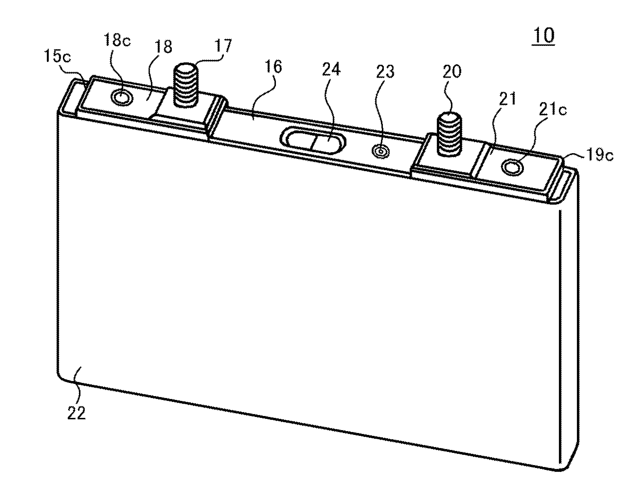
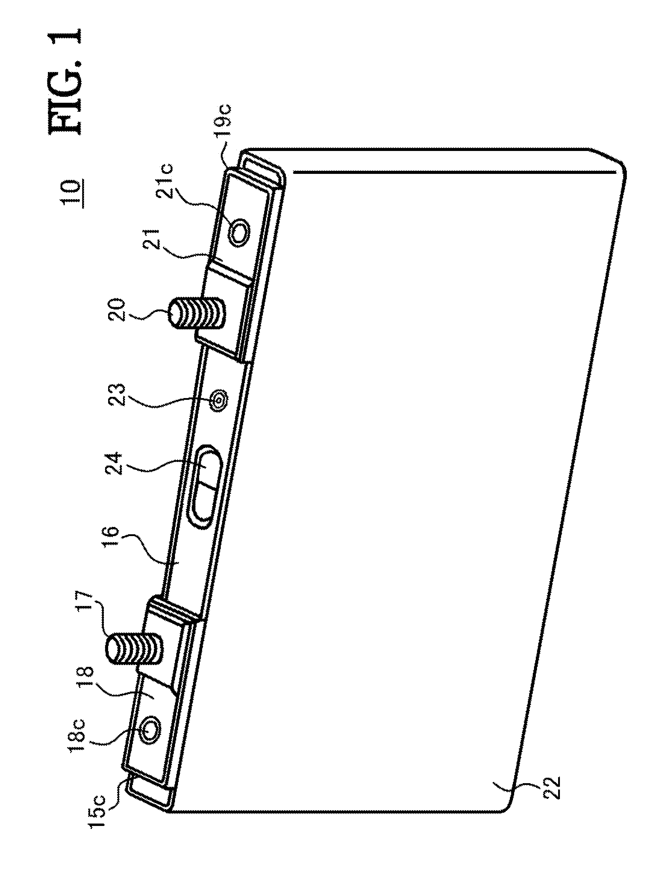
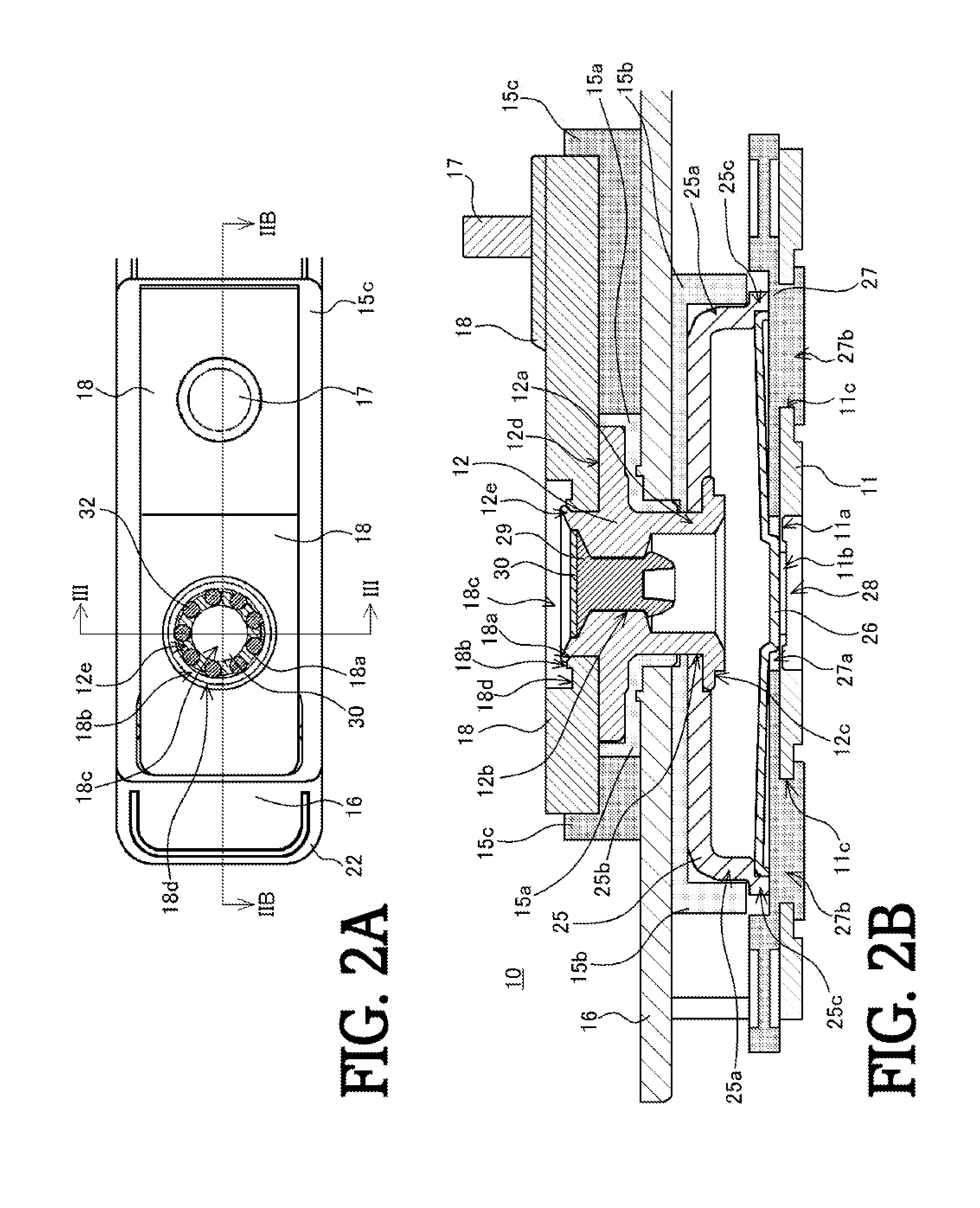
[0066]The prismatic secondary battery of the present invention is described below by a working example and comparative example, with reference to the accompanying drawings. The prismatic secondary battery illustrated below, however, offers the illustrative example of a prismatic non-aqueous electrolyte secondary battery serving as the prismatic secondary battery, in order for the technical concept of the present invention to be understood, and the present invention is not intended to be limited to being the prismatic non-aqueous electrolyte secondary battery; rather, the present invention can be equally well applied to a variety of modifications that are carried out without departing from the technical concepts illustrated by the claims.

[0067]Also, the prismatic secondary battery as in the present invention can be applied to a prismatic secondary battery having an electrode assembly given a flattened shape by laminating or winding a positive electrode plate and a negative electrode ...


PUM


Abstract

A groove is formed in a ring shape and a ring-shaped convexity is formed on the periphery of a through-hole of a positive electrode terminal plate. An upper end side of a crimping part of a positive electrode exterior terminal is inserted through the through-hole of the positive electrode terminal plate and crimped, and welded spots are formed by irradiation with high-energy beams between a distal end side of the crimping part and the convexity. The mechanical and electrical connection of an exterior terminal and a terminal plate to the crimping part through welding with high-energy beams makes it possible to provide a prismatic secondary battery of enhanced reliability in which cracking is less likely to occur in the welded spots, the coupling strength between the exterior terminal and the terminal plate is increased, and fluctuations in the internal resistance are curbed.

Description

TECHNICAL FIELD[0001]The present invention relates to a prismatic secondary battery provided with a coupling part where an exterior terminal and a terminal plate is connected by crimping and welding by high-energy beams.BACKGROUND ART[0002]Alkaline secondary batteries, which are typified by nickel-hydrogen batteries, and non-aqueous electrolyte secondary batteries, which are typified by lithium ion batteries, are often used as a drive power source for portable electronics, such as portable telephones, including smartphones, as well as portable computers, personal digital assistants (PDA), and portable music players. Alkaline secondary batteries and non-aqueous electrolyte secondary batteries are also often used in stationary storage battery systems such as for applications for curbing fluctuations in the output of power sources for driving electric vehicles (EVs) and hybrid electric vehicles (HEVs, PHEVs), solar power generation, wind power generation, and the like, peak-shifting ap...

Claims


Application Information

Patent Timeline
IPC IPC(8): H01M2/30H01M50/176H01M50/534H01M50/55H01M50/553H01M50/562H01M50/566
CPCH01M2/30Y02E60/10H01M50/103H01M50/562H01M50/534H01M50/55H01M50/553H01M50/176H01M50/566
Inventor HATTORI, TAKAYUKIHOSOKAWA, HIROSHIYAMAUCHI, YASUHIRO
Owner SANYO ELECTRIC CO LTD
Why Eureka
Try Eureka