Exposure data acquisition method and electronic equipment

A technology for exposing data and electronic equipment, applied to TVs, electrical components, color TVs, etc., can solve the problem of wasting effective use of screen area

Active Publication Date: 2020-06-09
VIVO MOBILE COMM HANGZHOU CO LTD
View PDF6 Cites 4 Cited by
  • Summary
  • Abstract
  • Description
  • Claims
  • Application Information

AI Technical Summary

Problems solved by technology

[0005] The purpose of the present invention is to provide a method for acquiring exposure data and electronic equipment, so as to solve the problem that ...

Method used


Image

  • Exposure data acquisition method and electronic equipment
  • Exposure data acquisition method and electronic equipment
  • Exposure data acquisition method and electronic equipment

Examples


Embodiment Construction

[0033] The following will clearly and completely describe the technical solutions in the embodiments of the present invention with reference to the accompanying drawings in the embodiments of the present invention. Obviously, the described embodiments are some of the embodiments of the present invention, but not all of them. Based on the embodiments of the present invention, all other embodiments obtained by persons of ordinary skill in the art without creative efforts fall within the protection scope of the present invention.

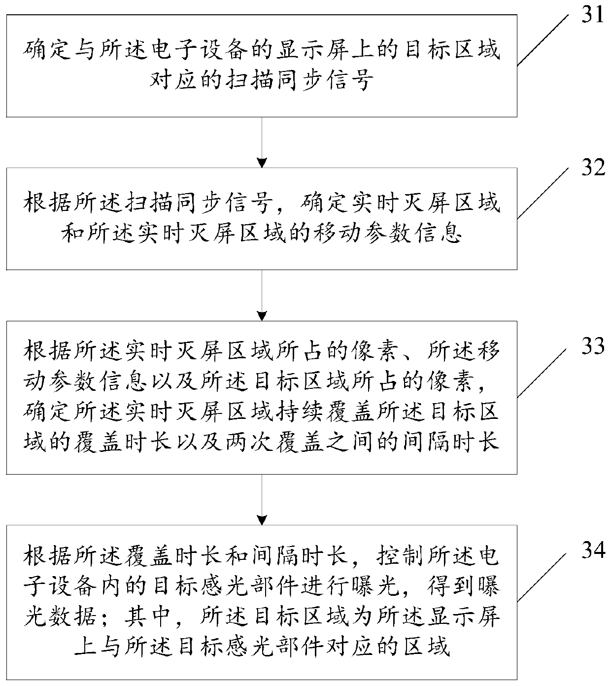
[0034] The present invention aims at the problem that the exposure implementation scheme of the photosensitive device in the electronic equipment wastes the effective use area of ​​the screen in the existing technology, and provides an exposure data acquisition method, which is applied to the electronic equipment, such as image 3 shown, including:

[0035] Step 31: Determine a scanning synchronization signal corresponding to the target area on the dis...


PUM


Abstract

The invention provides an exposure data acquisition method and electronic equipment. The method comprises the steps: determining a scanning synchronization signal corresponding to a target region on adisplay screen of electronic equipment; determining a real-time screen-off area and movement parameter information of the real-time screen-off area according to the scanning synchronization signal; according to pixels occupied by the real-time screen-off area, movement parameter information and pixels occupied by the target area, determining the covering duration of the target area continuously covered by the real-time screen-off area and the interval duration between the two times of covering; according to the coverage duration and the interval duration, controlling a target photosensitive part in the electronic equipment to perform exposure to obtain exposure data. The target area is an area, corresponding to the target photosensitive part, on the display screen. According to the scheme, a problem that in the prior art, an exposure implementation scheme of a photosensitive device in electronic equipment wastes the effective utilization area of a screen is well solved.

Description

technical field [0001] The present invention relates to the technical field of electronic equipment, in particular to an exposure data acquisition method and electronic equipment. Background technique [0002] In order to increase the screen ratio in current mobile terminals, water drop screens or hole-digging screens are often used, that is, space is reserved for the camera to receive light at the edge of the rectangular screen or the screen area, such as figure 1 shown (when not using the front camera). Because the screen will emit light when taking pictures, in order to reduce the stray light generated by the screen and diffract to the camera nearby, resulting in poor imaging effect, usually set a certain width of black border outside the camera acceptance angle (Fov) to absorb Stray light from the screen, such as figure 2 shown (when using the front camera). [0003] However, when taking a selfie on the front, setting the black border on the screen to absorb stray li...

Claims


Application Information

Patent Timeline
IPC IPC(8): H04N5/235H04N5/232
CPCH04N23/62H04N23/631H04N23/73H04M1/0264H04M1/0266H04M2250/52H04N23/57G06F3/147G09G3/20H04N23/72H04N23/71
Inventor 雷乃策
Owner VIVO MOBILE COMM HANGZHOU CO LTD
Why Eureka
Try Eureka