Bottom shape structure of thin-walled and thin-walled multi-layer co-injected plastic container

A plastic container and thin-wall technology, which is applied in the field of thin-wall and thin-wall multi-layer co-injection plastic containers, can solve the problems of uneven wall thickness, abrupt connection flow corners, increased energy consumption, etc., and achieve easy molding and uniform material distribution , the effect of increasing the flow length ratio

Pending Publication Date: 2020-06-12
GUANG DONG XING LIAN PRECISE MACHINERY
View PDF0 Cites 0 Cited by
  • Summary
  • Abstract
  • Description
  • Claims
  • Application Information

AI Technical Summary

Problems solved by technology

[0004] However, under the existing injection molding equipment conditions and injection molding process conditions, the flow length ratio of plastic products is difficult to achieve the optimal flow length ratio
For example, the flow length ratio of single-layer and multi-layer plastic products injected with PP plastic can only reach about 180. The reason is that the connection between two adjacent structures at the bottom of the plastic products currently on the market It is an edge, that is, it is connected through an edge. Such a connection flow angle is relatively abrupt, which not only affects the pressure loss and flow rate, but also increases the shear stress inside the plastic product and increases energy consumption; and poor fluidity also leads to single-layer products. The injection molding at the front end is not full, the bottom of the middle layer of the multi-layer product is accumulated and thick, the middle layer is not easy to flow and extend to the front of the container, and the flow front is uneven and the height difference is large, and the wall thickness is uneven

Method used


Image

  • Bottom shape structure of thin-walled and thin-walled multi-layer co-injected plastic container
  • Bottom shape structure of thin-walled and thin-walled multi-layer co-injected plastic container
  • Bottom shape structure of thin-walled and thin-walled multi-layer co-injected plastic container

Examples


Embodiment Construction

[0029] The technical solution of the present invention will be explained more clearly and completely through the description of preferred embodiments of the present invention in conjunction with the accompanying drawings.

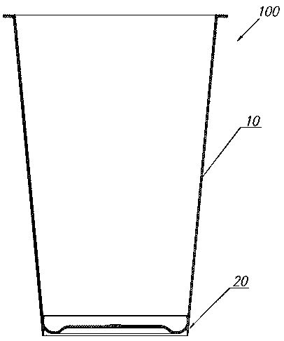
[0030] Such as figure 1 As shown, the thin-walled and thin-walled multi-layer co-injection plastic container 100 of the present invention includes a container side wall 10 and a container bottom 20 .

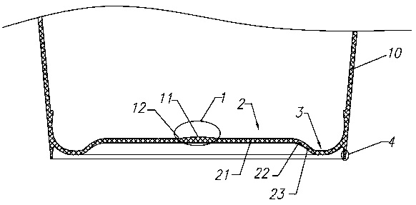
[0031] The shape and structure of the container bottom 20 includes a bottom central depression area 2 , bottom transition bottom corners 3 , and feet 4 . The feet 4 are in contact with a desktop or other supports, and are used to support the plastic container 100 on the supports. The bottom central recessed area 2 is located in the circular area surrounded by the feet 4 and is recessed toward the opening of the plastic container 100 . The bottom central recessed area 2 is connected to the bottom foot 4 through the bottom surface transition corner 3 .

[00...


PUM


Abstract

The invention provides a bottom shape structure of a thin-walled and thin-walled multi-layer co-injected plastic container. The bottom shape structure comprises a bottom central recessed area, a bottom transitional bottom corner position, and footings; the bottom central recessed area is connected with the footings through the bottom transitional bottom corner position; the bottom central recessedarea is provided with a bottom central sprue; the bottom central sprue is bulged toward an opening direction of the container to form a bulge, thus forming a bottom central sprue concave arc position; and the bottom of the bulge is in circular arc transition with the bottom central recessed area. The bottom shape structure effectively increases the flow length ratio, enables a product to be likely to be molded and full, and is uniform in material distribution.

Description

technical field [0001] The invention relates to a thin-walled and thin-walled multi-layer co-injection plastic container, in particular to a bottom shape structure of a thin-walled and thin-walled multi-layer co-injected plastic container. Background technique [0002] With the rapid development of the plastics industry and the continuous improvement of plastic properties, plastic products have been widely used. Most plastic products are molded by injection molding. For the injection molding process, the flow length ratio of plastic is very important, which directly affects the wall thickness and quality of plastic products. [0003] The flow length ratio of plastic refers to the ratio of the length of plastic melt flow to the wall thickness. The smaller the flow length ratio, the worse the fluidity of the plastic melt. The flow length ratio of different plastics is different, for example: the flow length ratio of LDPE is 270, the flow length ratio of HDPE is 230, the flow...

Claims


Application Information

Patent Timeline
Patent Type & Authority Applications(China)
IPC IPC(8): B65D1/40
CPCB65D1/40
Inventor 谢国基姜晓平刘勇涂小庭卢佳
Owner GUANG DONG XING LIAN PRECISE MACHINERY
Why Eureka
Try Eureka