Arc-type sprue mould

A mold and gate technology, which is applied in the field of light guide plate forming equipment and molds, can solve the problems of cutting head scrapping, balance, and inability to respond to glue discharge, etc., and achieve the effect of uniform injection and increased flow ratio

Inactive Publication Date: 2017-06-27
WUXI BOTEWEI PHOTOELECTRIC TECH CO LTD
View PDF1 Cites 0 Cited by
  • Summary
  • Abstract
  • Description
  • Claims
  • Application Information

AI Technical Summary

Problems solved by technology

[0002] The gates currently designed are designed in parallel regardless of the size of the rectification area at the glue outlet, which cannot cope with the balance of the glue outlet when the finished light guide plate is changed. In particular, the gates of the existing 7-inch 0.48T light guide plate general mold gates are all large gates. The main design is to achieve the purpose of balance of raw material discharge and stable forming during injection molding, but the corresponding gate cutting knife also needs to use a 150 mm special tool to cope with a gate as long as 120 mm, and The trimmed material head (6.8g) accounts for 42.5% of the weight of the single-piece injection material (15.98g), resulting in the scrapping of the trimmed material head

Method used


Image

  • Arc-type sprue mould
  • Arc-type sprue mould
  • Arc-type sprue mould

Examples


Embodiment Construction

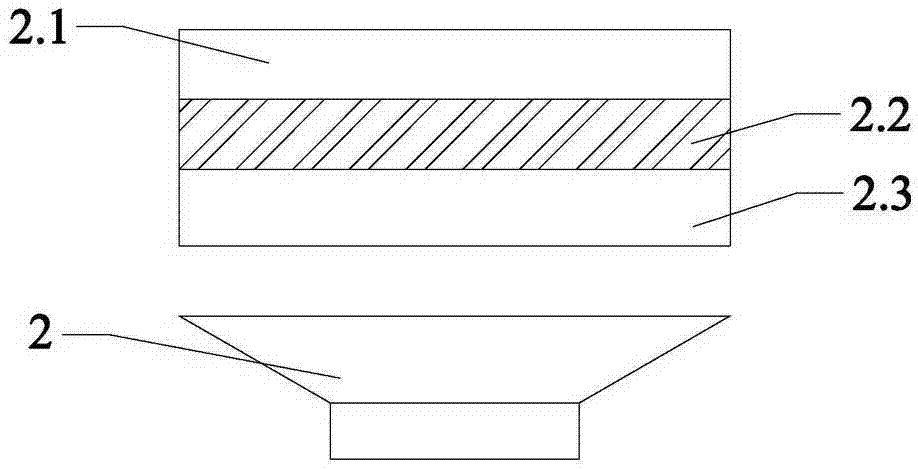
[0011] Depend on figure 1 It can be seen that the existing gate 2, its glue inlet 2.2 is: the depth of glue inlet in the middle and both ends is equal, preferably 4.6mm;

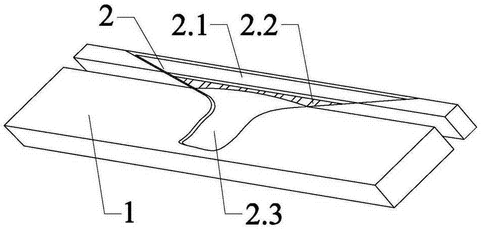
[0012] Depend on figure 2 It can be seen that the present invention includes a mold body 1 and a gate 2, the gate 2 is arranged on the mold body 1, the opening of the gate 2 has a smooth arc of 0.10mm, and the front end of the gate 2 is filled with glue It includes: fixed side 2.1, movable side 2.3, glue inlet 2.2 located between the fixed side 2.1 and movable side 2.3, the movable side 2.3 is an arc structure bent toward the glue inlet 2.2, It can be adjusted according to the size variation of the finished product, so as to facilitate injection adjustment and mass production.

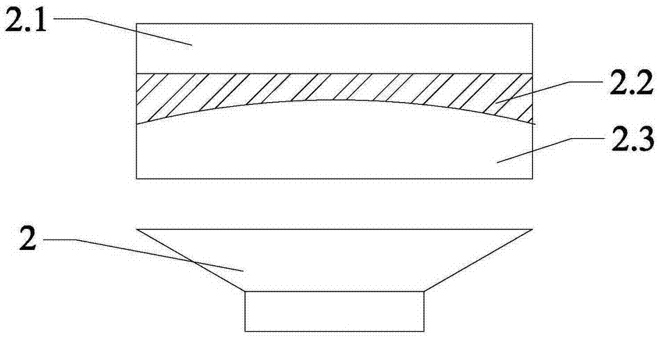
[0013] Depend on image 3 It can be seen that the glue feeding depth at both ends of the glue inlet 2.2 is 0.4-0.5 mm, preferably 0.46 mm; the glue feeding depth in the middle of the glue inlet 2.2 is 0.3-0.4 mm, preferably 0.36 ...


PUM


Abstract

The invention provides an arc-type sprue mould, including a mould body and a sprue. The sprue is arranged on the mould body. At the front end of the sprue, a glue inlet zone includes a fixed side, a movable side, and a glue inlet port arranged therebetween. The movable side has an arc-shaped structure bended towards the glue inlet port. By means of the arc shape design of the opening, glue inlet depth has asymmetry at the two ends and the middle of the sprue, so that when a raw material flows through the two ends and the middle of the sprue, the raw material is balanced and flow-length ratio of a position, being far away from the sprue, of a finish product is increased, so that material ejection is more uniform. In practical application, scrapping rate of material heads is greatly reduced and procedure usage rate after a small cutting knife is increased.

Description

technical field [0001] The invention mainly relates to the field of light guide plate molding equipment and moulds, in particular to an arc-type gate mold, which overcomes the problem of uneven gate discharge during injection molding of light guide plates. Background technique [0002] The gates currently designed are designed in parallel regardless of the size of the rectification area at the glue outlet, which cannot cope with the balance of the glue outlet when the finished light guide plate is changed. In particular, the gates of the existing 7-inch 0.48T light guide plate general mold gates are all large gates. The main design is to achieve the purpose of balance of raw material discharge and stable forming during injection molding, but the corresponding gate cutting knife also needs to use a 150 mm special tool to cope with a gate as long as 120 mm, and The trimmed head (6.8g) accounts for 42.5% of the weight of the single-piece injection material (15.98g), resulting i...

Claims


Application Information

Patent Timeline
IPC IPC(8): B29C45/27
CPCB29C45/27
Inventor 华军
Owner WUXI BOTEWEI PHOTOELECTRIC TECH CO LTD
Why Eureka
Try Eureka