Stove flue gas collection device and biomass burning furnace

A biomass combustion furnace and ash discharge device technology, applied in the field of combustion furnaces, can solve the problems of large difference in flue pressure, uneven heating of cooking pots, etc., and achieve good environmental protection performance, stable work, and reduced dust emissions.

Active Publication Date: 2018-09-18
孙吉章
View PDF9 Cites 0 Cited by
  • Summary
  • Abstract
  • Description
  • Claims
  • Application Information

AI Technical Summary

Problems solved by technology

Due to the position and quantity of the flue gas outlet, the flue gas pressure in each area of ​​the furnace varies greatly, that is, the resistance to the flow of flue gas in each area of ​​the furnace varies greatly, and the flame tends to the flue gas outlet, causing the cooking pot to be heated. uneven

Method used


Image

  • Stove flue gas collection device and biomass burning furnace
  • Stove flue gas collection device and biomass burning furnace

Examples


Embodiment 1

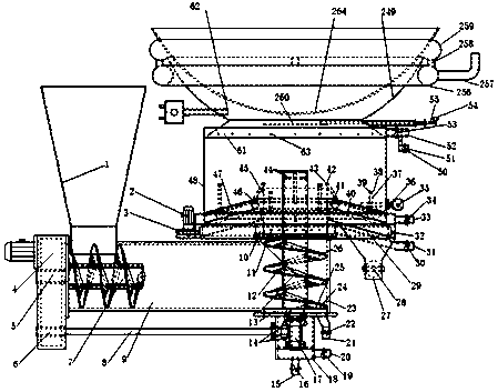
[0030]The upper end of the vertical feed pipe 23 is connected with the lower end of the furnace feed pipe 45, and the lower end of the vertical feed pipe 23 is connected with the vertical spiral support 18. The side of the vertical feed pipe 23 has a feed inlet and is connected with the horizontal feed pipe 9, and the other end of the horizontal feed pipe 9 is connected with the gearbox 4 and the funnel 1 respectively. The horizontal screw 7 is connected with the A output end 5 of the gearbox, and the horizontal screw 7 is flexibly connected with the horizontal feed pipe 9 . One end of the transmission shaft 8 is connected with the B output end 6 of the gearbox, and the other end is connected with one of the bevel gear sets 14, and the other end of the bevel gear set 14 is connected with the lower end of the vertical helix 26, and the transmission shaft 8 is connected with the vertical helix Bearing 18 is flexibly connected. One end of the chip removal valve B 16 is connected...


PUM


Abstract

The invention discloses a cooking range flue gas collecting device and a biomass combustion furnace. The cooking range flue gas collecting device is characterized in that an opening of an opening-shaped upper hearth is pot-shaped, and an upper port and a hearth is connected with a bottom port of the opening-shaped upper hearth. The cooking range flue gas collecting device has the benefits that the opening of the opening-shaped upper hearth is pot-shaped, an annular furnace brim is arranged at the top end of the opening of the opening-shaped upper hearth, and the cross section of the annular furnace brim is in an arc structure. A plurality of annular flue gas pipe connectors are arranged in the same horizontal circumference below the furnace brim, annular flue gas pipes are connected with the annular flue gas pipe connectors, and flue gas outlets are connected with the annular flue gas pipes and are not aligned to the annular flue gas pipe connectors, thereby allowing flue gas pressure in a flue gas emission channel to be balanced and the trends of flames in the hearth to be uniform.

Description

technical field [0001] The invention belongs to a solid fuel combustion furnace, and relates to a fully automatic feed biomass combustion furnace in which the fuel is combusted from top to bottom, in particular to a stove flue gas collection device and a biomass combustion furnace. Background technique [0002] Existing stoves that produce flames in the hearth of biomass burning furnaces all use a flue gas outlet at a certain position on the upper part of the hearth to discharge the flue gas by connecting them to a chimney. Due to the position and quantity of the flue gas outlet, the flue gas pressure in each area of ​​the furnace varies greatly, that is, the resistance to the flow of flue gas in each area of ​​the furnace varies greatly, and the flame tends to the flue gas outlet, causing the cooking pot to be heated. uneven. [0003] Therefore, the prior art scheme also needs to be further improved. Contents of the invention [0004] The object of the present invention...

Claims


Application Information

Patent Timeline
Patent Type & Authority Patents(China)
IPC IPC(8): F24B1/191F24B1/197
CPCF24B1/191F24B1/1915F24B1/197
Inventor 孙清刚陆振邦孙吉章
Owner 孙吉章
Why Eureka
Try Eureka