Reinforced Composite Stamp for Dry Transfer Printing of Semiconductor Elements
a technology of reinforced composite stamps and semiconductor elements, which is applied in the direction of turning machines, turning machine accessories, drawing profiling tools, etc., can solve the problems of insufficiently addressing the need for in-plane rigidity and vertical flexibility of conventional stamps, and achieve precise and repeatable vertical motion of the patterned surface, excellent control of relative spatial placement accuracy, and uniform distribution of contact force
- Summary
- Abstract
- Description
- Claims
- Application Information
AI Technical Summary
Benefits of technology
Problems solved by technology
Method used
Image
Examples
example 1
Reinforced Composite Stamps
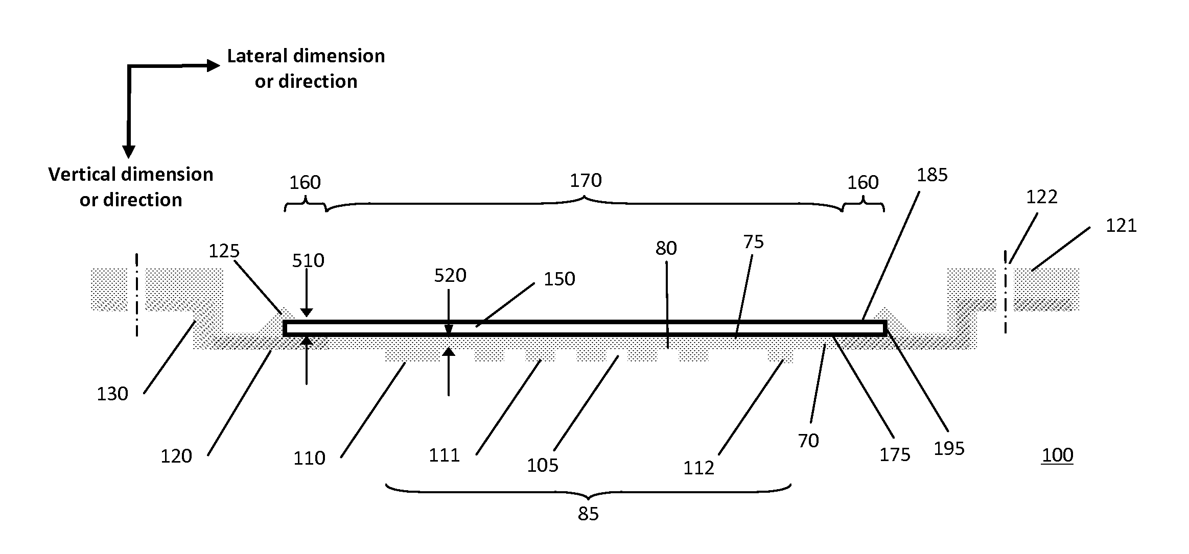
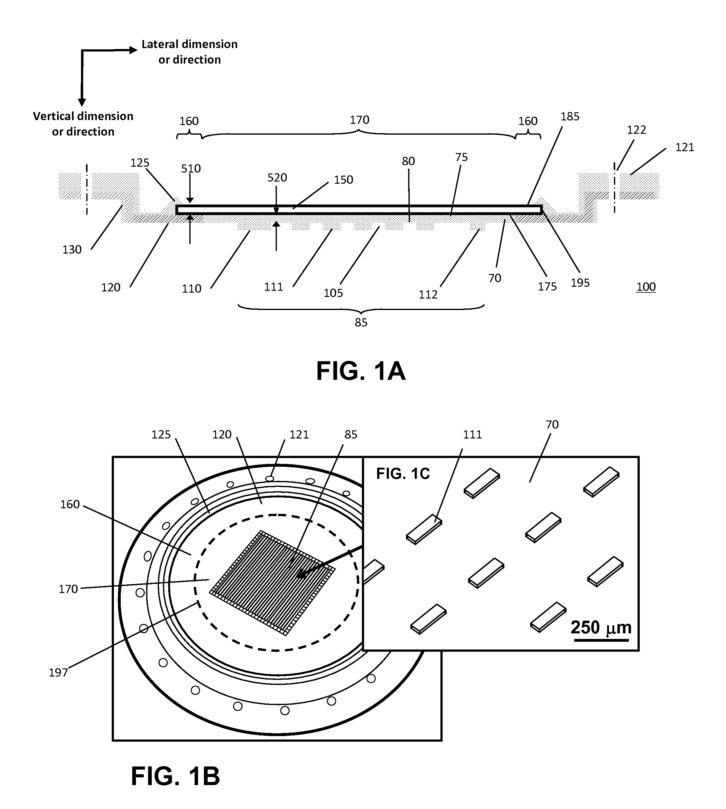
[0093]FIG. 1A provides a schematic cross-sectional view of an exemplary reinforced composite stamp 100 of the present invention. As shown in FIG. 1A, the composite stamp comprises a deformable layer 70, a reinforcement layer 120, and a rigid support layer 150. An array of relief features 105 are defined on the external surface 80 of the deformable layer 70 to facilitate selective transfer of printed structures, such as semiconductor elements. Array of relief features 105 may comprise a relief pattern providing selective printing or patterning functionality. External surface 80 is the surface of deformable layer 70 configured such that it is that is capable of contacting donor or target substrates for dry-transfer printing processes, for example providing a contact surface, printing surface or receiving surface of stamp 100 for dry transfer contact printing. The deformable layer 70 also has an internal surface 75 that faces rigid support layer 150. As shown...
example 2
Devices for Printing Using Reinforced Composite Stamps
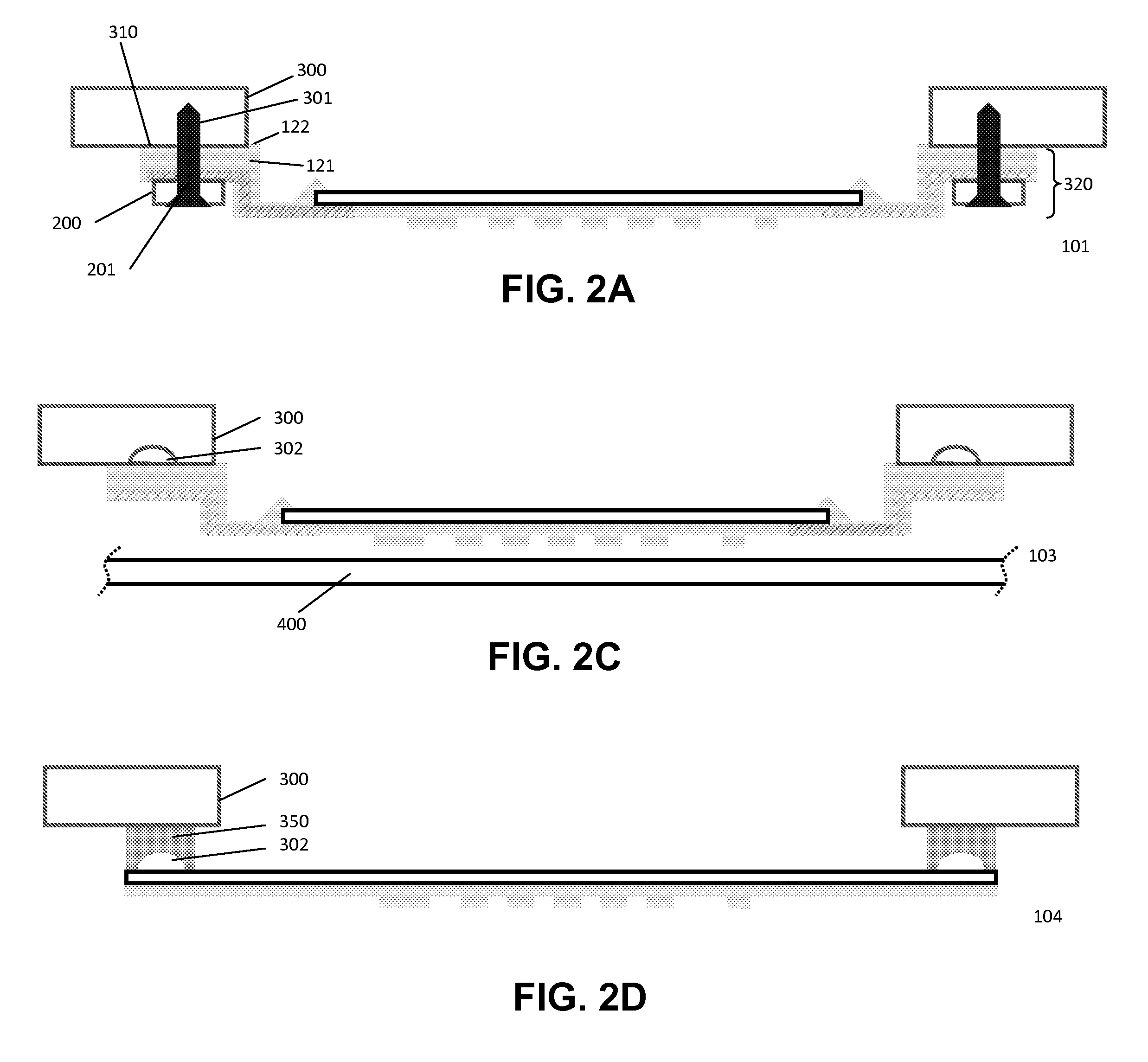
[0102]FIGS. 2A-D provides a schematic cross-sectional view of a reinforced composite stamp illustrating different examples of how a stamp of FIG. 1 is attached to a transfer printing tool head apparatus 300. Such a system can be used for a wide variety of printing methods, including dry transfer printing methods related to conformal contact with a target or a donor substrate, illustrated by 400 in FIG. 2C, where the dashed lines indicate the target or donor substrate extends and has a surface area that is larger than the printable area 85 or surface area of deformable layer 70. In each of the exemplified embodiments, the stamp and mounting design ensures there is adequate clearance distance 320 between a target substrate 400 positioned in contact with the relief features and the apparatus to which the stamp is mounted, thereby facilitating printing to a target substrate that has a surface area that is larger than the printable su...
example 3
Devices for Making Reinforced Composite Stamps
[0107]Provided herein are examples of systems and processes that can be used to make reinforced composite stamps of the present invention. FIG. 3 is a schematic illustration of a set of parts used in the process of making or molding reinforced composite stamps. One example of the steps used to make a reinforced composite stamp are as follows:
[0108]A master 402, for example a patterned master is fabricated using standard techniques, such as a UV photo-lithographic process (as described in published lithography literature; see, e.g., US Pat. Pub. No. 20060286785 to Rogers et al.). In an embodiment, master 402 is a patterned silicon wafer having relief features corresponding to the relief feature pattern desired for the deformable stamp patterned surface.
[0109]The master 402 is placed with the surface 425 having the relief feature pattern facing down in a wafer holder subassembly 403. An example wafer holder subassembly 403 is machined stai...
PUM
| Property | Measurement | Unit |
|---|---|---|
| thickness | aaaaa | aaaaa |
| thickness | aaaaa | aaaaa |
| thickness | aaaaa | aaaaa |
Abstract
Description
Claims
Application Information
 - R&D
- Intellectual Property
- Life Sciences
- Materials
- Tech Scout
- Unparalleled Data Quality
- Higher Quality Content
- 60% Fewer Hallucinations
Browse by: Latest US Patents, China's latest patents, Technical Efficacy Thesaurus, Application Domain, Technology Topic, Popular Technical Reports.
© 2025 PatSnap. All rights reserved.Legal|Privacy policy|Modern Slavery Act Transparency Statement|Sitemap|About US| Contact US: help@patsnap.com


