Connection structure of prefabricated assembly type laminated plates and steel beam and connection method thereof

A technology of prefabricated assembly and connection structure, which is applied to floors, building components, building structures, etc., can solve problems such as the bad influence of the connection between the prefabricated bottom plate and the steel beam, and the joint performance of the prefabricated bottom plate. Improve interoperability, reduce lateral stretch and vertical vibration damage, and shorten construction period

Inactive Publication Date: 2020-06-16
XIAN UNIV OF TECH
View PDF8 Cites 2 Cited by
  • Summary
  • Abstract
  • Description
  • Claims
  • Application Information

AI Technical Summary

Problems solved by technology

[0005] The purpose of the present invention is to provide a connection structure between prefabricated assembled laminated slabs and steel beams, which solves the problem in the prior art that the poor connection between the prefabricated bottom slab and the steel girder affects the performance of their cooperative work and the relationship between the prefabricated bottom slabs. Problems prone to cracks at joints

Method used


Image

  • Connection structure of prefabricated assembly type laminated plates and steel beam and connection method thereof
  • Connection structure of prefabricated assembly type laminated plates and steel beam and connection method thereof
  • Connection structure of prefabricated assembly type laminated plates and steel beam and connection method thereof

Examples


Embodiment Construction

[0035] The present invention will be described in detail below in conjunction with the accompanying drawings and specific embodiments.

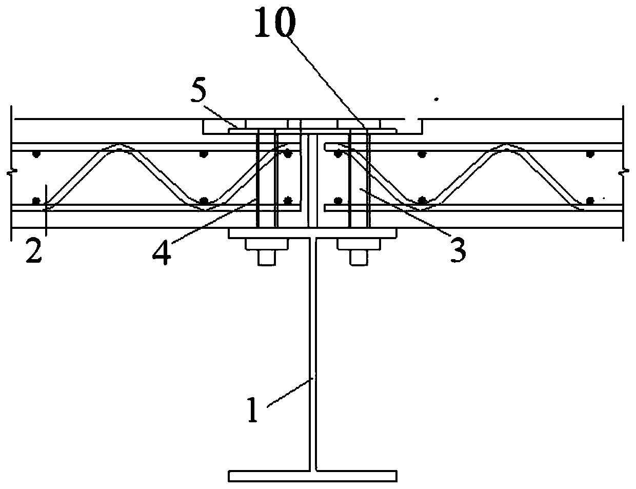
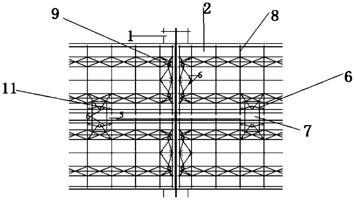
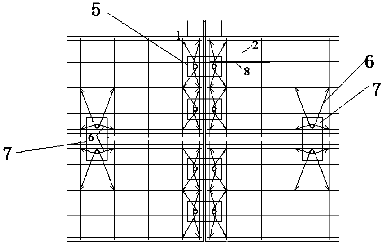
[0036] The present invention is a connection structure between a prefabricated assembled laminated plate and a steel beam, the structure of which is as follows Figure 1-3 As shown, including the I-shaped steel beam 1, the upper surface of the I-shaped steel beam 1 "I" is left-right symmetrical and fixed with a reinforced truss concrete composite plate 2 through a bolt connector 3;

[0037] The reinforced truss concrete composite slab 2 is fixed on the I-shaped steel beam 1, and one end of the I-shaped steel beam 1 is reserved with a through hole 9, and a casing 4 is anchored in the through hole 9, and the casing 4 extends out of the reinforced truss concrete composite slab 2. On the upper surface, the upper surface of two symmetrical steel bar truss concrete laminates 2 is jointly covered with a cover plate 5, and a hole 10 is opened on the ...


PUM


Abstract

The invention discloses a connection structure of prefabricated assembly type laminated plates and a steel beam. The connection structure comprises an H-shaped steel beam, the H-shaped upper surface of the H-shaped steel beam is fixedly provided with the reinforced truss concrete laminated plates in a bilateral symmetry mode, and the ends, fixed to the H-shaped steel beam, of the reinforced trussconcrete laminated plates are provided with through holes. Sleeves are anchored in the through holes. The sleeves extends out of the upper surfaces of the reinforced truss concrete laminated plates, the upper surfaces of the two reinforced truss concrete laminated plates are covered with a cover plate together, and the positions, corresponding to the through holes, on the cover plate are providedwith holes. Bolt connecting pieces sequentially penetrate through the holes and the sleeves to be fixed to the H-shaped upper surface of the H-shaped steel beam. The connection structure solves the problems that in the prior art, connection of prefabricated bottom plates and the steel beam is not good, accordingly the performance of cooperative work is affected and cracks are prone to occurring atjoints of the prefabricated bottom plates. The invention further discloses a connection method of the connection structure of the prefabricated assembly type laminated plates and the steel beam.

Description

technical field [0001] The invention belongs to the technical field of construction engineering, and relates to a connection structure between a prefabricated and assembled laminated plate and a steel beam, and also relates to a connection method of the above-mentioned laminated plate. Background technique [0002] As the country puts forward the requirements of building industrialization, all kinds of prefabricated floors emerge in endlessly. At present, the floors of buildings generally have problems such as poor overall rigidity, poor stability and earthquake resistance, low load-bearing capacity, and high cost. , It is difficult to take measures at the joints of the floor slabs in the project, resulting in poor sound insulation of the building. [0003] Prefabricated concrete laminated floor is one of the most commonly used floor forms of prefabricated steel structure houses, and it is also the first research content in the floor system. It has good integrity, crack resi...

Claims


Application Information

Patent Timeline
Patent Type & Authority Applications(China)
IPC IPC(8): E04B5/10
CPCE04B5/10
Inventor 田建勃王梦梦王振山郭宏超胡孔斌李慎
Owner XIAN UNIV OF TECH
Why Eureka
Try Eureka