Camera module and electronic equipment

A camera module and lens group technology, applied in the camera field, can solve the problem of reducing the size of the module and equipment

Active Publication Date: 2020-06-19
GUANGDONG OPPO MOBILE TELECOMM CORP LTD
View PDF7 Cites 9 Cited by
  • Summary
  • Abstract
  • Description
  • Claims
  • Application Information

AI Technical Summary

Problems solved by technology

[0003] The embodiment of the present application provides a camera module and electron

Method used


Image

  • Camera module and electronic equipment
  • Camera module and electronic equipment
  • Camera module and electronic equipment

Examples


Example Embodiment

[0048] In order to facilitate the understanding of the application, the application will be described in a more comprehensive manner with reference to the relevant drawings. The drawings show preferred embodiments of the application. However, this application can be implemented in many different forms and is not limited to the embodiments described herein. On the contrary, the purpose of providing these embodiments is to make the understanding of the disclosure of this application more thorough and comprehensive.

[0049] It should be noted that when an element is referred to as being "fixed to" another element, it may be directly on the other element or a central element may also exist. When an element is considered to be "connected" to another element, it can be directly connected to the other element or an intermediate element may be present at the same time. The terms "vertical", "horizontal", "left", "right" and similar expressions used herein are for illustrative purposes...


PUM


Abstract

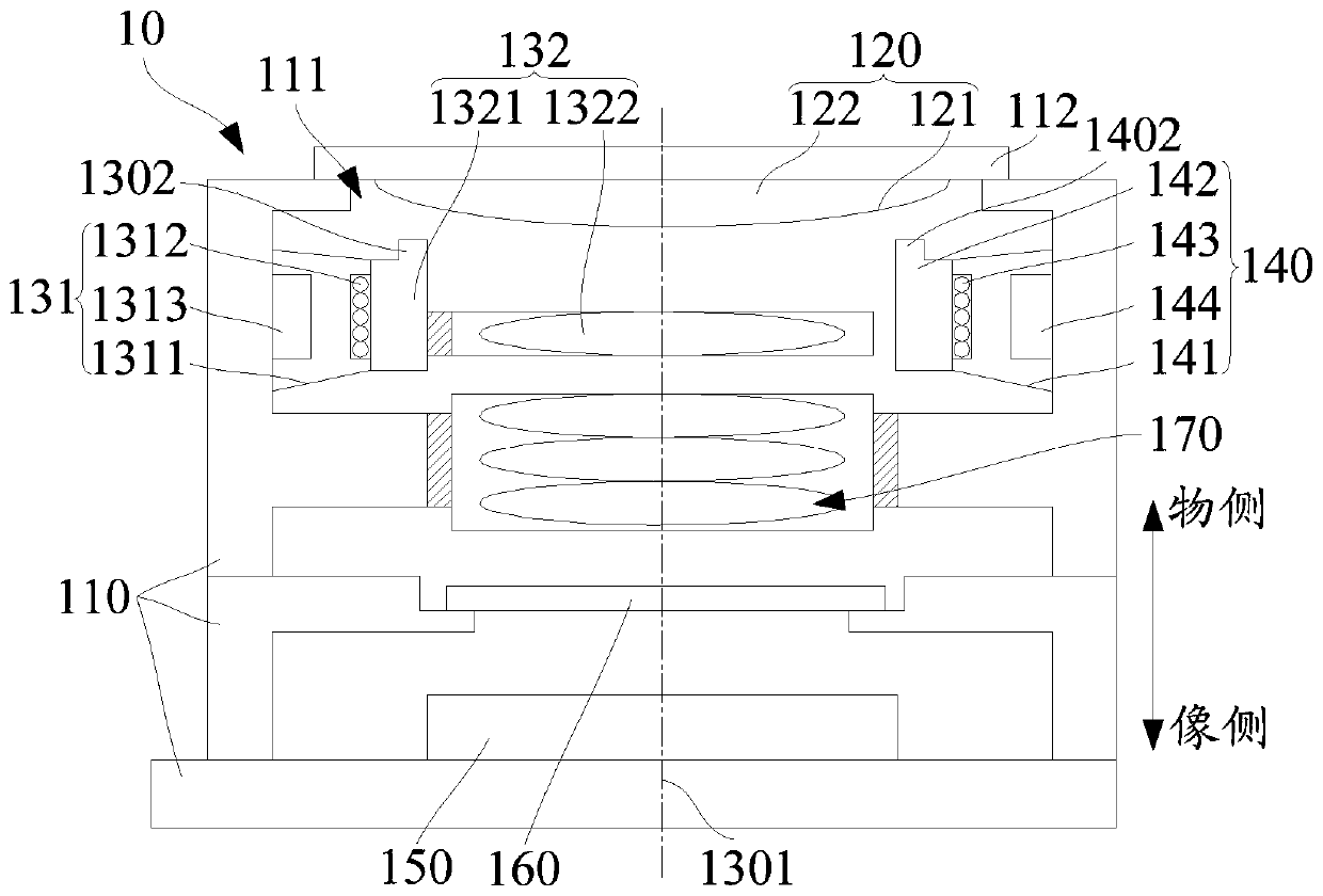
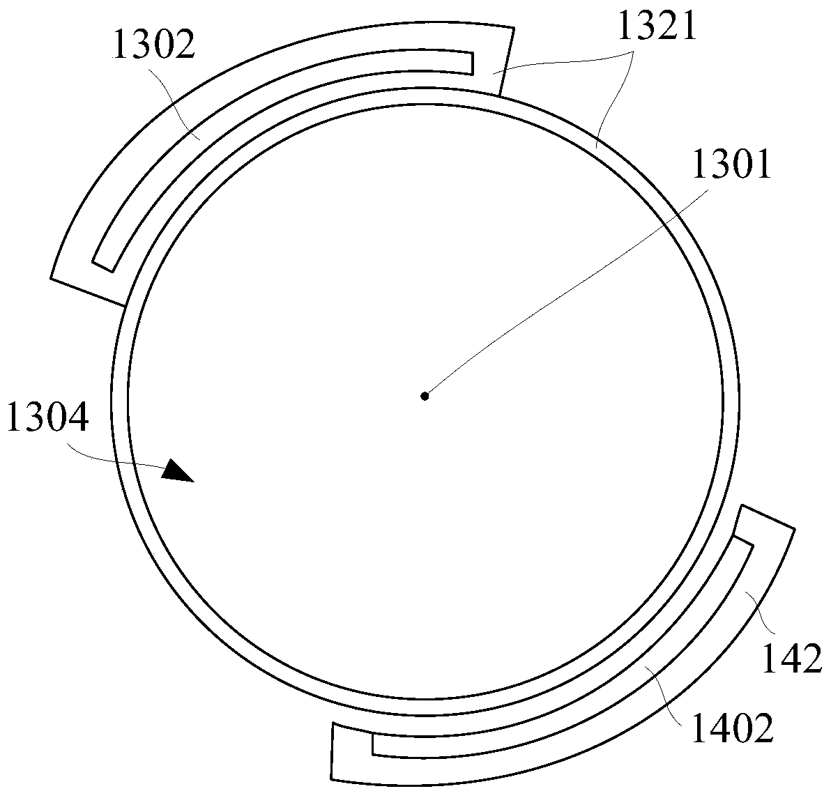
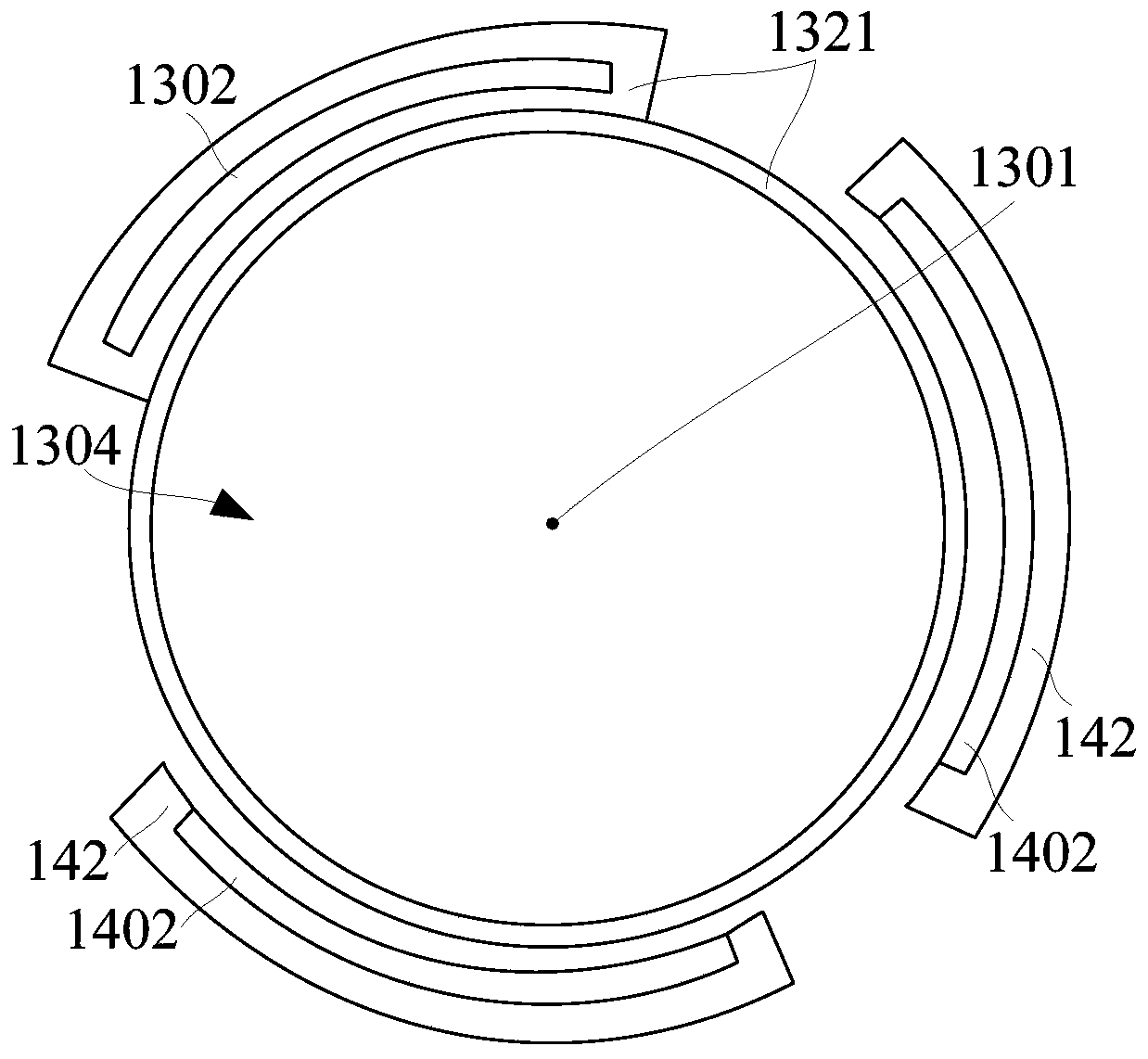
The invention relates to a camera module and electronic equipment. The camera module comprises a lens seat; a liquid lens which is connected with the lens base and comprises a closed bag body and liquid arranged in the closed bag body; a first pressing element which comprises a first driving piece and a first lens group, a second pressing element which is connected to the lens seat, and an image sensor which is arranged on one side, far away from the liquid lens, of the first pressing element and is connected with the lens seat, wherein the first driving piece is connected with the lens seat and the first lens group; the first lens group comprises a first pressing part and at least one lens arranged on the first pressing part, the optical axis of the first lens group is a first optical axis, the liquid lens is arranged on an object side of the first lens group along the direction of the first optical axis, the first driving piece can drive the first lens group to move along the direction of the first optical axis so as to enable the first pressing element to press the liquid lens, the second pressing element and the first pressing element are arranged at intervals, and the second pressing element can press the liquid lens in the direction of the first optical axis. The camera module has a large zoom range and can realize miniaturized design.

Description

technical field [0001] The present application relates to the field of photography, in particular to a camera module and electronic equipment. Background technique [0002] The traditional camera module achieves the zoom effect by setting the driving member to change the relative position of the lens of the moving part. Generally, a camera module with a zoom effect requires a large lens movement space, which leads to an excessively large axial dimension of the module, which restricts the miniaturization design of the device (such as reducing the thickness of the device), and cannot meet the market demand for electronics. Requirements for equipment miniaturization design. Contents of the invention [0003] Embodiments of the present application provide a camera module and electronic equipment to solve the problem of how to reduce the size of the module and the equipment. [0004] A camera module, comprising: [0005] Mirror mount; [0006] A liquid lens, connected to th...

Claims


Application Information

Patent Timeline
IPC IPC(8): G03B13/34G02B26/00H04N5/225
CPCG03B13/34G02B26/004H04N23/54H04N23/55
Inventor 陈伟
Owner GUANGDONG OPPO MOBILE TELECOMM CORP LTD
Why Eureka
Try Eureka