Supercharge Your Innovation With Domain-Expert AI Agents!

Methods for sparse arrays of circular shape

A circular shape and array technology, which is applied in the field of sparse circular shape arrays, can solve problems such as finding the optimal solution and entering a local minimum

Active Publication Date: 2021-07-06
NANJING UNIV OF SCI & TECH
View PDF5 Cites 0 Cited by
  • Summary
  • Abstract
  • Description
  • Claims
  • Application Information

AI Technical Summary

Problems solved by technology

There is also a dynamic programming method that can optimize arrays with a large number of array elements, but it is very easy to enter the local minimum and not find the optimal solution

Method used


Image

  • Methods for sparse arrays of circular shape
  • Methods for sparse arrays of circular shape
  • Methods for sparse arrays of circular shape

Examples


Embodiment

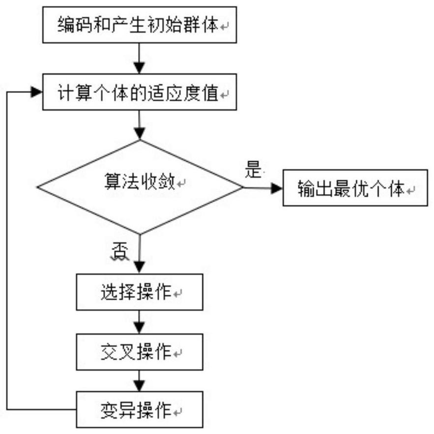
[0031] The genetic algorithm is used to sparsely arrange the uniform circular array to achieve the purpose of reducing the number of antenna array elements, effectively reducing the cost, and suppressing the sidelobe level of the antenna pattern of the array antenna at the azimuth plane.

[0032] Only consider the direction diagram of the circular array azimuth plane, M represents the number of circular array elements, m represents the mth array element, Φ represents the direction angle, (φ 0 , θ 0 ) is the direction angle of the azimuth plane, λ is the signal electromagnetic wavelength, R is the radius of the circular array, γ m is the angle between the line between the mth array element and the center of the circle and the x-axis, then the array pattern function can be expressed as:

[0033]

[0034] For sparse optimization of uniformly arranged circular array antennas, use f m Indicates the working status of the corresponding array element: f m =1 indicates that there...


PUM


Abstract

The invention discloses a method for thinning circular arrays, using genetic algorithm to sparse arrays of circular rings and cylindrical arrays, comprising the following steps: setting initial values ​​for circular rings or cylindrical arrays; using genetic algorithms for sparse arrays ; Obtain the sparse array result and the pattern function. The invention uses the genetic algorithm to carry out circular sparse array arrangement, effectively reduces antenna array elements, lowers cost, and at the same time suppresses grating lobes to obtain a low side lobe pattern.

Description

technical field [0001] The invention relates to antenna array thinning technology, in particular to a method for thinning circular arrays. Background technique [0002] In radar and communication systems, in order to make the antenna have high gain, narrow beam, low side lobe and other characteristics, array antennas are widely used. In order to ensure that there is no angular ambiguity in direction finding, etc., the internal array element spacing of the uniform array cannot be greater than half the wavelength of the incident signal. Therefore, the aperture of the array is limited by the number of elements. The larger the aperture of the array, the higher the resolution of the incoming signal. For a uniform array, in order to obtain a super-resolution DOA estimation effect, the number of array elements must be increased. In this way, not only the hardware cost will be greatly increased, but also the array design will be very difficult. The spacing between the array elem...

Claims


Application Information

Patent Timeline
Patent Type & Authority Patents(China)
IPC IPC(8): H01Q21/00G06T3/00G06N3/12
CPCG06N3/126G06T3/0012H01Q21/00
Inventor 缪晨沈凯
Owner NANJING UNIV OF SCI & TECH
Features
  • R&D
  • Intellectual Property
  • Life Sciences
  • Materials
  • Tech Scout
  • Unparalleled Data Quality
  • Higher Quality Content
  • 60% Fewer Hallucinations
Learn More