
Modular planar array sparse optimization method and system

A planar array, sparse optimization technology, applied in antenna array, design optimization/simulation, electrical components, etc., can solve the problem that the position of the resulting unit is random and irregular, reduce the number and cost of large-scale radar array elements, and super-large-scale array There are no problems such as engineering realization, so as to achieve the effects of reducing processing costs, improving optimization efficiency, and strong anti-interference ability

Pending Publication Date: 2021-01-05
CHINA ELECTRONIC TECH GRP CORP NO 38 RES INST
View PDF0 Cites 0 Cited by
  • Summary
  • Abstract
  • Description
  • Claims
  • Application Information

AI Technical Summary

Problems solved by technology

However, each unit is an antenna unit and an active channel component. Ultra-large-scale arrays will lead to high costs for the entire radar system. The sparse design of the array is an effective method to effectively reduce the number and cost of large-scale radar array elements.
[0003] In the existing sparse array optimization scheme, all array elements can be randomly arranged in any position in the target area. After the optimization algorithm obtains new individuals based on crossover and mutation, it needs to judge whether the minimum distance between array elements satisfies the distance limit condition. When the limit distance is large When the judgment process takes a lot of time, the optimization efficiency is low
Although this scheme has a large degree of freedom in the arrangement of array elements, the operation is also very difficult; when the array element spacing is large, the optimization result is easy to fall into the local optimal solution, and it is difficult to obtain the global optimal solution
In addition, in order to meet the requirements of the system for side lobes, the position of the resulting units of the current sparse array is random and irregular, and there is no possibility of engineering realization for ultra-large-scale arrays

Method used


Image

  • Modular planar array sparse optimization method and system
  • Modular planar array sparse optimization method and system
  • Modular planar array sparse optimization method and system

Examples


Embodiment 1

[0063] This embodiment provides a sparse optimization method for a modularized planar array, and finally obtains the element distribution of the optimal sparse array and the array pattern at the time of the lowest sidelobe.

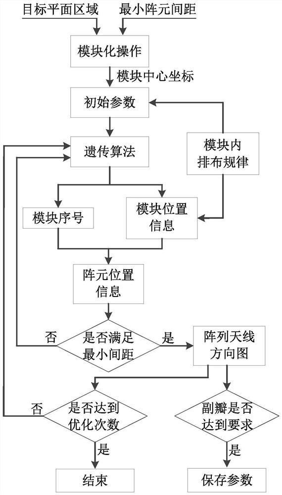
[0064] Such as figure 1 as shown, figure 1 It is a flow chart of the sparse optimization method for modularized planar arrays in this embodiment, and the method includes the following steps:

[0065] S1: Modular operation

[0066] Divide the target area into modules of uniform shape and size, and output the location information of all modules. The specific steps are as follows:

[0067] (1) Establish a two-dimensional Cartesian coordinate system on the plane where the target area is located, and set the x-axis and y-axis;

[0068] (2) Set the shape and size of the module: the shape of the module needs to meet the splicability, and there is no gap and no overlap between adjacent modules after splicing; the default shape is rectangle;

[0069] (3) Divid...

Embodiment 2

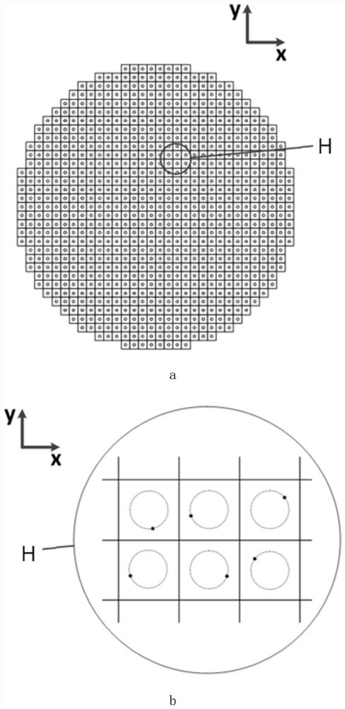
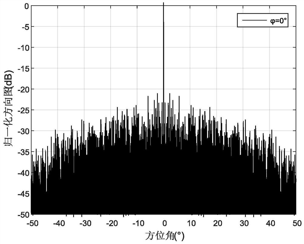
[0089] In this embodiment, the performance of the circular aperture array antenna pattern is optimized, the frequency point to be optimized is f, and the corresponding wavelength is λ. Set the x-axis and y-axis as figure 2 shown. The diameter of the target array is 2500λ, the shape of the modules is square, and the size is 10λ×10λ. The modules are arranged in a rectangular grid. After the modular operation, the total number of modules is 48833. Each module is numbered, each number corresponding to its position. The number of antenna elements to be optimized is 500, the target sidelobe is -20dB, and the pattern to be optimized is normal and cut surface, optimization coefficient α i Both are 1. In order to improve the degree of freedom of the position of the array element, the array element is placed on the ring with the center of the circle in each module and the radius of 3.5λ. The variables that determine the position information of each array element are the connecti...

Embodiment 3

[0093] In this embodiment, the performance of the pattern of the elliptical aperture array antenna is optimized, and the frequency point to be optimized is 15 GHz. The length of the major axis of the ellipse is 30m, the length of the minor axis is 20m, the shape of the module is square, and the size is 130mm×130mm. Set the x-axis and y-axis as Figure 5 As shown, the boundaries of the modules are parallel to the x-axis and the y-axis respectively, and there may be staggered between two adjacent rows of modules. After the modular operation, the total number of modules is 27,802. Each module is numbered, each number corresponding to its position. The number of antenna elements to be optimized is 550, the target sidelobe is -20dB, and the pattern to be optimized is Cut plane normal and scan 30°, optimization coefficient α i Both are 1. In order to improve the degree of freedom of the position of the array element, the array element is placed along four diagonal lines (A: upp...


PUM


Abstract

The invention discloses a modular planar array sparse optimization method and system, and belongs to the field of array antenna design, and the method comprises the following steps: S1, modular operation; S2, initial optimization of parameters; and S3, optimization calculation. The method and the system have high efficiency when being applied to sparse optimization of a large planar array antenna,under the condition that the sparsity is lower than 2%, the sidelobe level can reach -20dB or below, the minimum distance between every two array elements is smaller than an expected value, and the array radiation performance can be improved; a target plane is divided into a plurality of modules by adopting modular operation, and the shape and the size of each module are uniform, so that the later processing cost is reduced; the method and the system are suitable for a large radar system and a radio astronomical system, can greatly reduce the weight and cost of the system, improves the engineering realizability, and are worthy of popularization and application.

Description

technical field [0001] The invention relates to the technical field of array antenna design, in particular to a sparse optimization method and system for a modular planar array. Background technique [0002] In order to improve the observation distance and resolution of the radar, modern radar requires an increasing scale of the antenna array, and the number of units of many large radars reaches the order of more than 10,000. In order to obtain a larger field of view and a more flexible working mode, the field of radio astronomy has also begun to transform from traditional large-scale transmitting surface antennas to ultra-large-scale planar arrays. However, each unit is an antenna unit and an active channel component. Ultra-large-scale arrays will lead to high costs for the entire radar system. The sparse design of the array is an effective way to effectively reduce the number and cost of large-scale radar array elements. [0003] In the existing sparse array optimization ...

Claims


Application Information

Patent Timeline
IPC IPC(8): G06F30/27H01Q21/00
CPCG06F30/27H01Q21/00
Inventor 靳学明方佳朱庆超王璐徐龙陶蕾金谋平戴跃飞
Owner CHINA ELECTRONIC TECH GRP CORP NO 38 RES INST
Features
  • Generate Ideas
  • Intellectual Property
  • Life Sciences
  • Materials
  • Tech Scout
  • Unparalleled Data Quality
  • Higher Quality Content
  • 60% Fewer Hallucinations
Learn More