Sub-array-level sparse array antenna pattern numerical method and system
An antenna pattern, sparse array technology, applied in CAD numerical modeling, special data processing applications, geometric CAD and other directions, can solve problems such as large amount of calculation, reduce the number of radar array elements, reduce algorithm parameter debugging time, improve The effect of efficiency
- Summary
- Abstract
- Description
- Claims
- Application Information
AI Technical Summary
Problems solved by technology
Method used
Image

Examples
Embodiment 1
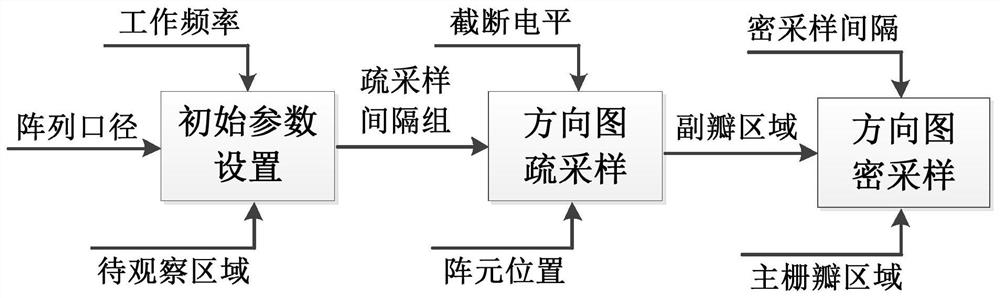
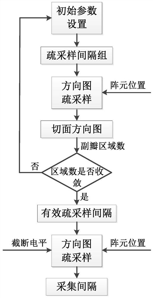
[0056] This embodiment provides a numerical method for a subarray-level sparse array antenna pattern, figure 1 It is a schematic flow chart of this embodiment, figure 2 Schematic diagram of the detailed process for sparse sampling of orientation maps. The operating frequency of the array antenna, the shape and size of the array aperture, and the area to be observed in the pattern are known. The array elements are arranged in the form of sub-arrays. The method for determining the positions of all array elements is as follows: first determine the number of sub-arrays and the number of array elements in the sub-array, then obtain the corresponding position coordinates for the arrangement of array elements in the sub-array and the center position of the sub-array, and finally set Add the position of the center of the subarray to the position of the array elements in the subarray to get all the positions of the array elements. The arrangement of array elements in the sub-array a...
Embodiment 2
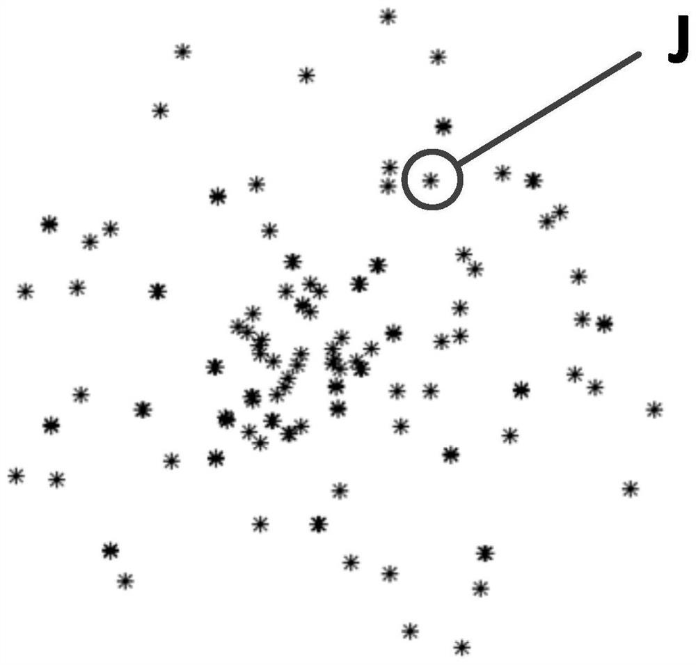
[0084] In this embodiment, the circular aperture sub-array-level sparse array antenna performance is calculated. The array elements in the sub-array are arranged in a dense array, and the working frequency is 10 GHz. The array antenna is arranged in the form of a sub-array, the shape of the sub-array is circular, and the array elements in the sub-array are arranged in a rectangular grid. The distance between array elements in the sub-array is 100mm, the radius of the sub-array is 850mm, and the number of elements in the sub-array is 198. The center position of the sub-arrays is known, the minimum spacing of the sub-arrays is 1800mm, and the number of sub-arrays is 100. The center of the initial subarray is located at the origin, and the initial subarray is copied to the center of each subarray in turn to obtain the array element position of the entire array antenna. The antenna section is φ=0°, the scanning state is normal, and the angle calculation interval is -45°~45°. The...
Embodiment 3
[0088] In this embodiment, the circular aperture sub-array-level sparse array antenna pattern performance is calculated, the array elements in the sub-array are sparsely arranged, and the working frequency point is 7 GHz. The array antenna is arranged in the form of a sub-array, the shape of the sub-array is circular, and the array elements in the sub-array are sparsely arranged. The minimum distance between array elements in the sub-array is 80mm, the radius of the sub-array is 450mm, and the number of elements in the sub-array is 16. The positions of the elements of the sub-array and the center of the sub-array are known, the minimum spacing of the sub-arrays is 980mm, and the number of sub-arrays is 1000. The center of the initial subarray is located at the origin, and the initial subarray is copied to the center of each subarray in turn to obtain the array element position of the entire array antenna. The antenna section is φ=0°, the scanning state is 30°, and the angle c...
PUM
 Abstract
Description
Claims
Application Information
PatSnap Eureka turns technology decisions into work you can execute. Powered by our Innovation Knowledge Graph, it runs expert workflows across engineering, life sciences, materials and intellectual property. Get your review-ready output in minutes.


