
Apparatus and method for generating hybrid modal vortex beams based on amplitude and phase control

A mixed-mode and vortex technology, which is applied in antenna grounding devices, specific array feeding systems, antenna arrays that are powered independently, etc., can solve the problems of large device size, difficult design of feeding network, unfavorable movement and maintenance, etc. Achieve the effect of reducing the number of array elements and simplifying the device

Inactive Publication Date: 2018-12-11
XIDIAN UNIV
View PDF1 Cites 2 Cited by
  • Summary
  • Abstract
  • Description
  • Claims
  • Application Information

AI Technical Summary

Problems solved by technology

However, this method requires a large number of antenna elements, and the device itself is large in size, which is not conducive to movement and maintenance, and it is difficult to design the feed network of the antenna array with a large number of elements.

Method used

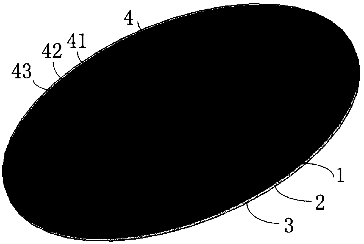
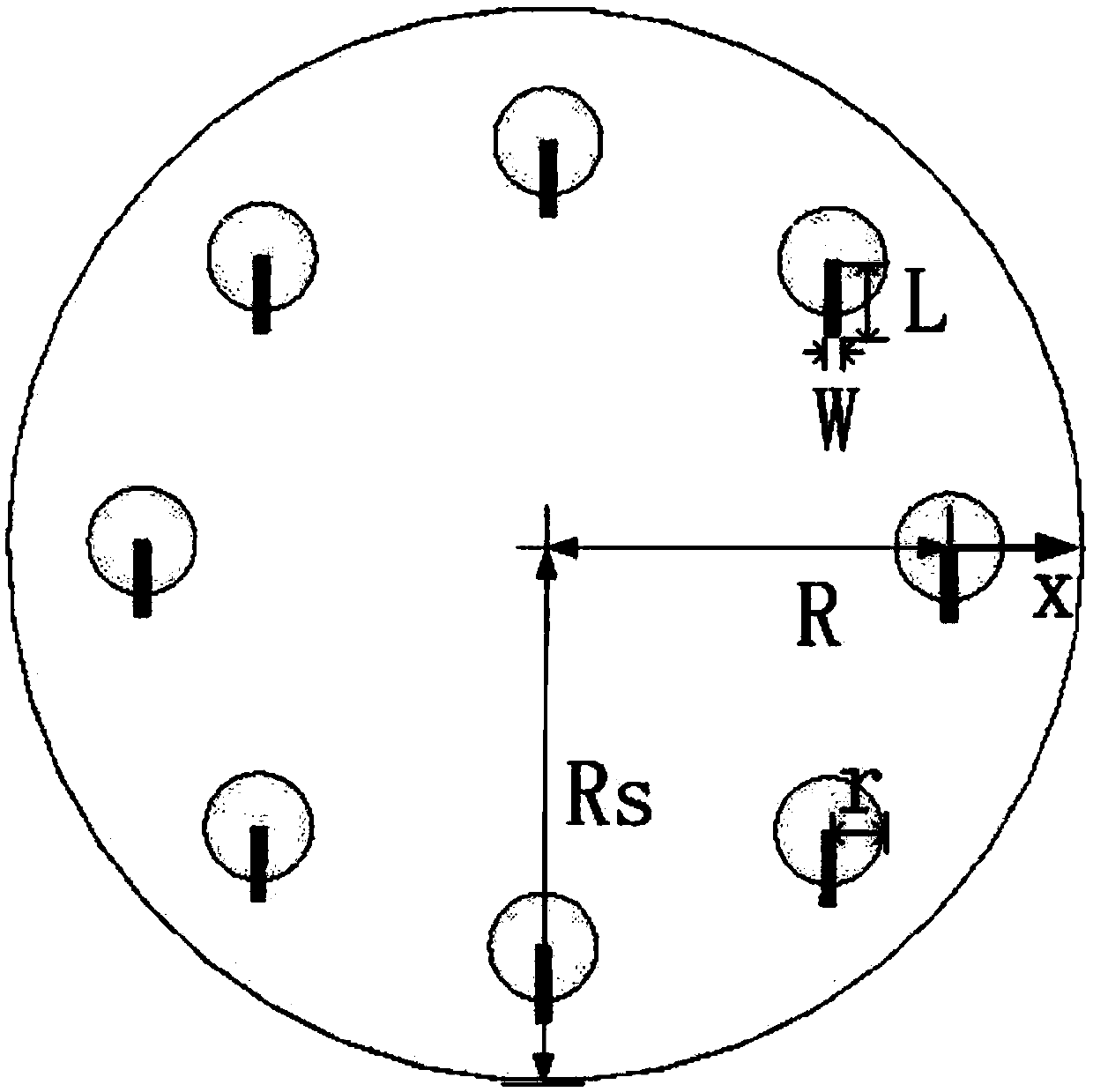
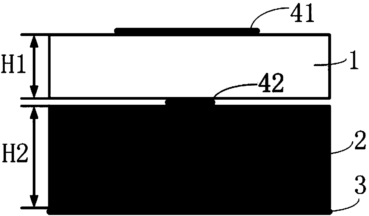

Image

  • Apparatus and method for generating hybrid modal vortex beams based on amplitude and phase control
  • Apparatus and method for generating hybrid modal vortex beams based on amplitude and phase control
  • Apparatus and method for generating hybrid modal vortex beams based on amplitude and phase control

Examples


Embodiment 1

[0049] In this example, the working frequency of the design center is f=5.8GHz, and the structural parameters are as follows:

[0050] The radius of the circular microstrip patch r=6.79mm; the length of the microstrip feeder L=10mm; the width W=1mm; the thickness of the first dielectric substrate H1=0.5mm; the thickness of the second dielectric substrate H2=2mm; the dielectric substrate Relative permittivity ε r = 4.4; the radius R of the circle where the microstrip antenna unit is distributed = 1.2λ = 62mm; the radius Rs of the first dielectric substrate and the second dielectric substrate = 76mm;

[0051] The number of microstrip antenna units N=8, the number of single-mode vortex waves contained in the mixed-mode vortex beam M=2, and the respective mode values ​​are: l 1 =+1, l 2 =-1.

[0052] For convenience, the number of the microstrip antenna unit on the x-axis is marked as 1, and the subsequent microstrip antenna units are numbered in counterclockwise order, and the...

Embodiment 2

[0059] In this example, the working frequency of the design center is f=5.8GHz, and the structural parameters are as follows:

[0060] The radius of the circular microstrip patch r=6.79mm; the length of the microstrip feeder L=10mm; the width W=1mm; the thickness of the first dielectric substrate H1=0.5mm; the thickness of the second dielectric substrate H2=2mm; the dielectric substrate Relative permittivity ε r = 4.4; the radius R of the circle where the microstrip antenna unit is distributed = 1.3λ = 67mm; the radius Rs of the first dielectric substrate and the second dielectric substrate = 80mm;

[0061] The number of microstrip antenna units N=8, the number of single-mode vortex waves contained in the mixed-mode vortex beam M=4, and the respective mode values ​​are: l 1 =+2,l 2 =+1,l 3 =-1,l 4 =-2.

[0062] For convenience, the number of the microstrip antenna unit on the x-axis is marked as 1, and the subsequent microstrip antenna units are numbered in counterclockwi...


PUM


Abstract

The invention discloses a device and a method for generating mixed mode vortex beams based on amplitude and phase control, which mainly solves the problem of excessive array elements of the mixed modevortex wave generating device in the prior art. The device comprises a two-layer dielectric substrate, a floor and a microstrip antenna unit. The microstrip antenna unit is uniformly arranged along acircular ring, and comprises a microstrip patch, a microstrip feed line and an input port. At first, that number of microstrip antenna elements, the numb of single mode vortex waves contained in themixed mode vortex wave and the modal value of each single mode vortex wave are determined; Then the amplitude and phase of the excitation signal for each microstrip antenna element are calculated. Theamplitude and phase are then applied to the input ports of each microstrip antenna element to couple the energy to the corresponding microstrip patch through a feed line connected to each input portto generate a hybrid modal vortex beam. The invention can generate mixed mode vortex beam through amplitude and phase control by using a single-loop uniform circular loop antenna array, and can be applied to wireless multiplexing communication.

Description

technical field [0001] The invention belongs to the technical field of wireless communication, and in particular relates to a device and method for generating a mixed-mode vortex beam, which can be used in a wireless communication system. Background technique [0002] Wireless communication technology has developed vigorously since its inception. People have designed the amplitude, frequency, phase, and polarization state of electromagnetic waves to realize the modulation and demodulation methods of multiplex communication, and successively proposed time division multiplexing, code division multiplexing, Technologies such as frequency division multiplexing have led to rapid growth in wireless communication rates and further expanded wireless communication services, bringing about tremendous changes in social life. At the same time, the rapid growth of wireless communication services has also led to increasingly scarce wireless spectrum resources, and has made the wireless co...

Claims


Application Information

Patent Timeline
Patent Type & Authority Applications(China)
IPC IPC(8): H01Q1/38H01Q1/48H01Q1/50H01Q21/00H01Q21/20
CPCH01Q1/38H01Q1/48H01Q1/50H01Q21/0006H01Q21/20
Inventor 李龙薛皓冯强席瑞刘永杰郑雨珊
Owner XIDIAN UNIV
Learn More