
Zipper lower stopper and quick-release zipper using same

A zipper and bottom stop technology, which is applied in the field of zippers, can solve the problems affecting the basic function of the bottom stop fastening, affecting the operation speed, and affecting the applicability, etc., to achieve rapid disengagement and fastening strength, enhance the lateral tensile strength, Taking into account the effect of splitting and buckling strength

Active Publication Date: 2020-06-23
FUJIAN ZIPPER SCI & TECH CO LTD
View PDF10 Cites 1 Cited by
  • Summary
  • Abstract
  • Description
  • Claims
  • Application Information

AI Technical Summary

Problems solved by technology

[0003] The pulling and disengaging operation of the existing zipper is not smooth enough in operation gestures, which affects the operation speed, especially in the disengaging action, which requires manual reverse (relative to the opening direction of the slider) operation, which cannot meet the requirements for fast pulling the zipper in practice. Engagement and Disengagement Functional Requirements
In addition, there is a certain conflict between the quick release function of the bottom stop and the fastening strength. In the current design of the bottom stop, on the basis of realizing quick release, there are usually insufficient buckling strengths, which affects the fastening of the bottom stop. Combine basic functions, and ultimately affect its actual applicability

Method used


Image

  • Zipper lower stopper and quick-release zipper using same
  • Zipper lower stopper and quick-release zipper using same
  • Zipper lower stopper and quick-release zipper using same

Examples


Embodiment Construction

[0036] Below in conjunction with specific embodiment, this case is described in further detail.

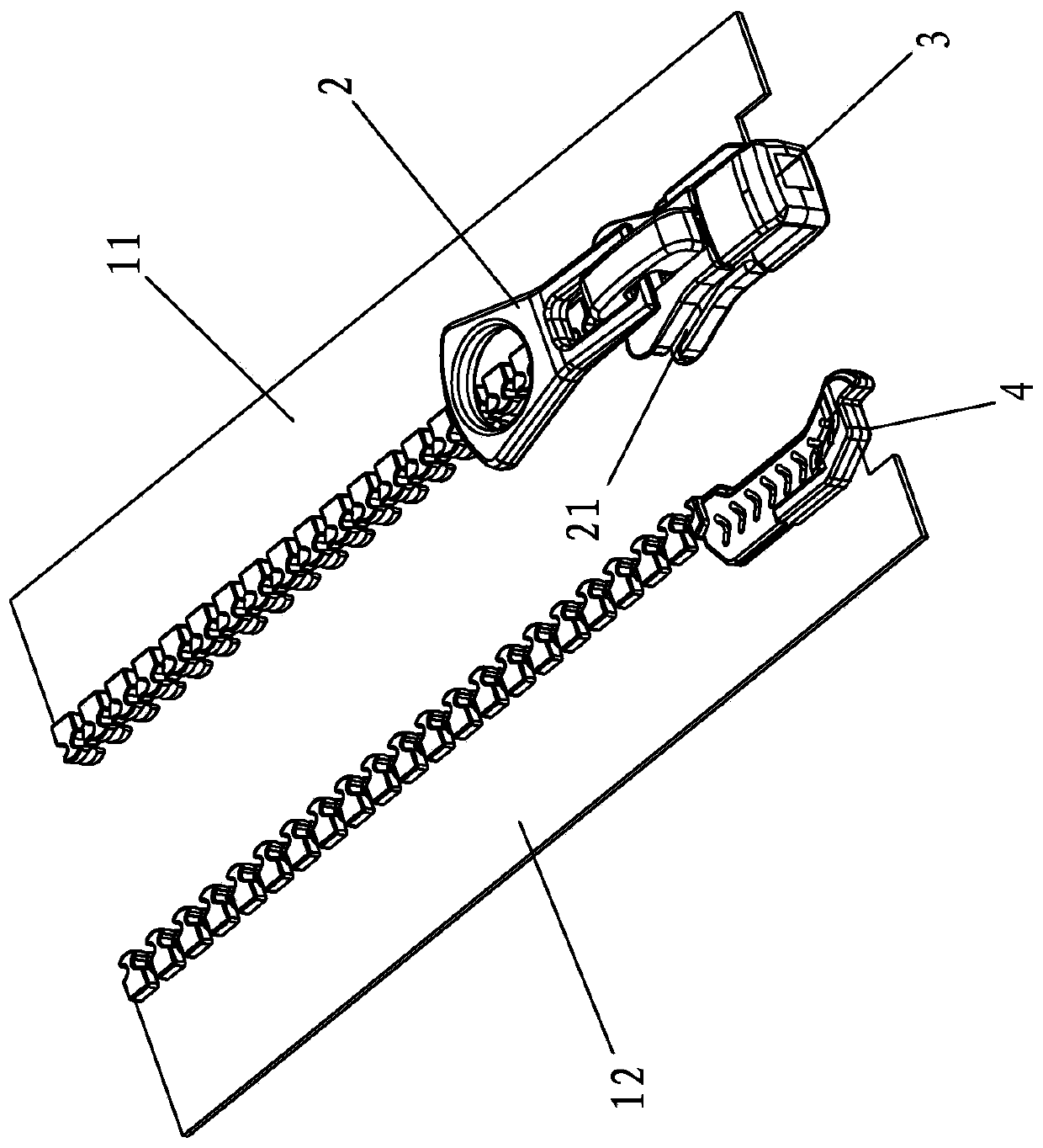
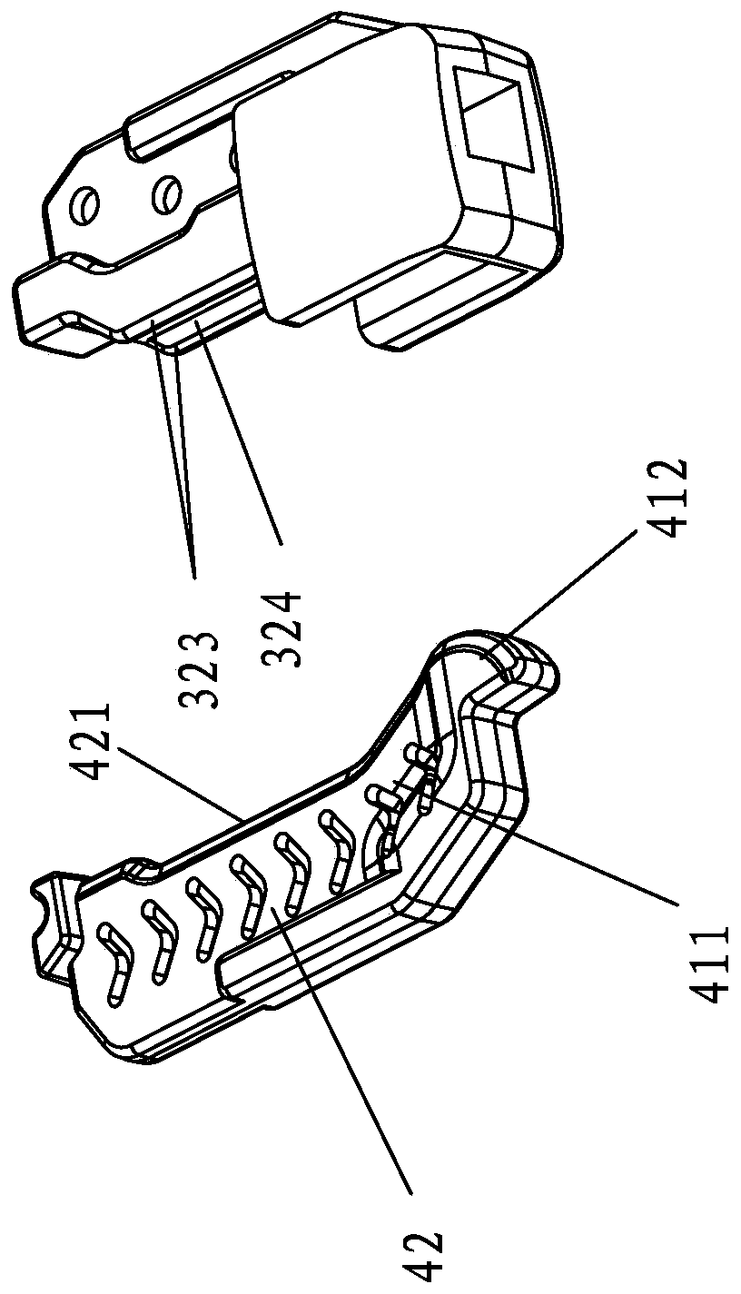
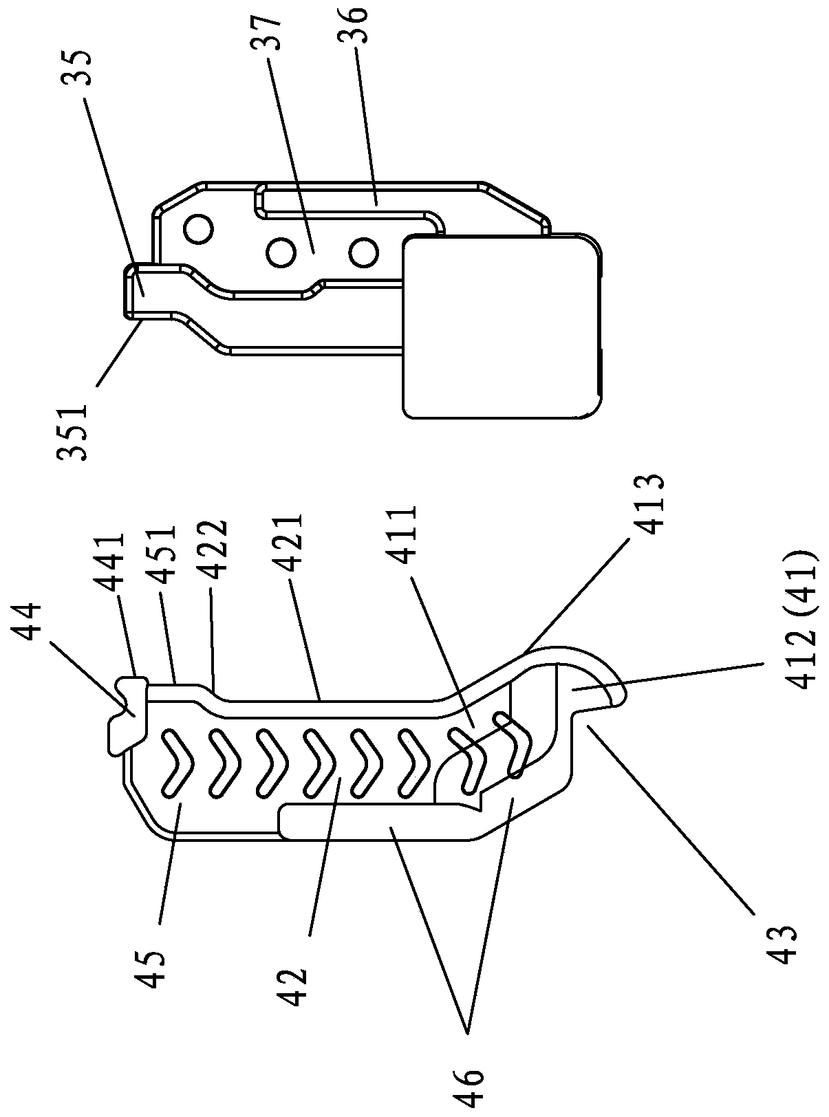
[0037] This case involves a quick release zipper, such as Figure 1-7 As shown, it includes two chain belts, slider 2 and bottom stop. The two chains are respectively a left chain 11 and a right chain 12, and the left chain 11 and the right chain 12 are respectively provided with a row of chain teeth capable of engaging with each other. The bottom stop includes a left stop 3 and a right stop 4, the left stop 3 and the right stop 4 are respectively arranged on the left chain belt 11 and the right chain belt 12 one by one, and the slider 2 is installed on the left chain belt 11 , the slider 2 has upper and lower ship plates, and the two sides of the upper and lower ship plates are respectively provided with a left side side groove and a right side side groove 21, and the slider 2 is installed on the left chain belt 11 through the left side side groove, and the right side The stopp...


PUM


Abstract

The invention discloses a zipper lower stopper and a quick-release zipper using the same, the lower stopper is provided with a middle reference line corresponding to a zipper occlusion middle position, and the lower stopper comprises a left stop piece and a right stop piece; an inserting groove and a left splicing part are arranged in front of and behind the left stop piece; a bolt and a right splicing part are arranged in front of and behind the right stop piece; the inner side track of the bolt is a convex arc, the right stop piece can be movably and obliquely inserted into the inserting groove through the bolt and rotates leftwards to be spliced with the left stop piece, and in the splicing state, the arc of the bolt extends to the left side of the middle reference line; an inner concave area is formed on the inner side of the right splicing part, an outer convex area is formed on the inner side of the left splicing part, the inner concave area and the outer convex area are splicedin a matched mode, and in the splicing state, the track line corresponding to the outer convex area is larger to the right side of the middle reference line, and a guide inclined face is formed at therear end of the outer convex area. According to the quick-release zipper, the purposes of quick splicing, quick release and high buckling strength are achieved.

Description

technical field [0001] The invention relates to the technical field of zippers, in particular to a bottom stop of a zipper and a quick release zipper using the bottom stop. Background technique [0002] In the zipper design, a zipper top stop component and a zipper bottom stop component are usually arranged at two ends of the zipper. The bottom stop component of the zipper is installed at the end of the two chain belts at the starting point of the slider, and is used to fasten the bottom ends of the separated two chain belts together before the slider starts, so that the two chain belts can be closed by the action of the slider. At present, the traditional zipper bottom stop assembly includes a pin and a socket, and the slider and the socket are arranged on the same chain belt. When the zipper is assembled, the slider and the socket are arranged close to each other, and the pin is first inserted through the slider from top to bottom, and then inserted into the socket and in...

Claims


Application Information

Patent Timeline
Patent Type & Authority Applications(China)
IPC IPC(8): A44B19/36A44B19/38
CPCA44B19/36A44B19/388
Inventor 邱润生刘拥华周兴旺张田
Owner FUJIAN ZIPPER SCI & TECH CO LTD
Learn More