Internal-bridging connection terminal structure

A technology for connecting terminals and terminals, applied in the direction of connection, clamping/spring connection, and components of connecting devices, etc., can solve the problems of complex lines, difficult to apply multiple wiring modes, etc., and achieve the effect of convenient on-site operation.

Pending Publication Date: 2020-06-23
DINKLE M&E CHINA
View PDF0 Cites 0 Cited by
  • Summary
  • Abstract
  • Description
  • Claims
  • Application Information

AI Technical Summary

Problems solved by technology

[0002] The clip structure terminal block in the traditional terminal block plug-in connector is a one-in-one-out wiring mode. If this structure needs to realize multiple groups of parallel connection lines, it is necessary to lead multiple wires from the power supply to connect separately, which leads to circuit breakers. Complicated and difficult to apply to multiple wiring modes

Method used


Image

  • Internal-bridging connection terminal structure
  • Internal-bridging connection terminal structure
  • Internal-bridging connection terminal structure

Examples


Embodiment 1

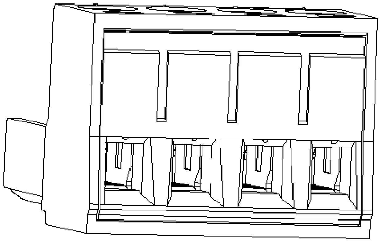
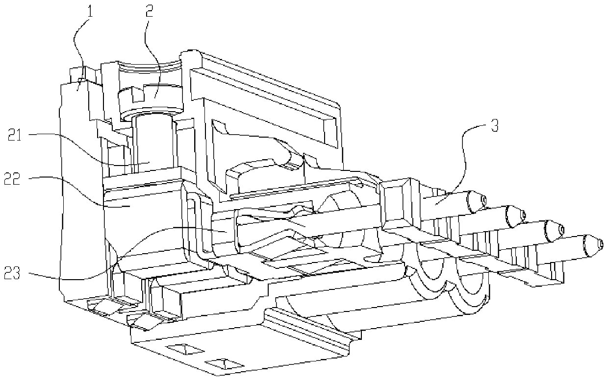
[0044] Embodiment 1: A screw-type internal bridging connection terminal structure, including a first terminal base body 1, the first terminal base body is made of insulating material, and a first clamping component 2 is arranged inside the first terminal base body , the clamping assembly 2 is composed of a bolt 21, a square box 22, and a first bridge structure terminal 23, and the screw 21, the square box 22, and the first bridge structure terminal 23 are arranged inside the first terminal base body 1 in a separated manner Therefore, the bolt 21, the square box 22 and the first bridge structure connection terminal 23 are separate components.

[0045] The first bridge structure connection terminal 23 comprises a first connection terminal 231, a second connection terminal 232 and a bridge structure 233 symmetrically arranged with the first connection terminal 231, wherein the bridge structure 233 is a pair of the first connection terminal 231 and the first connection terminal 231...

Embodiment 2

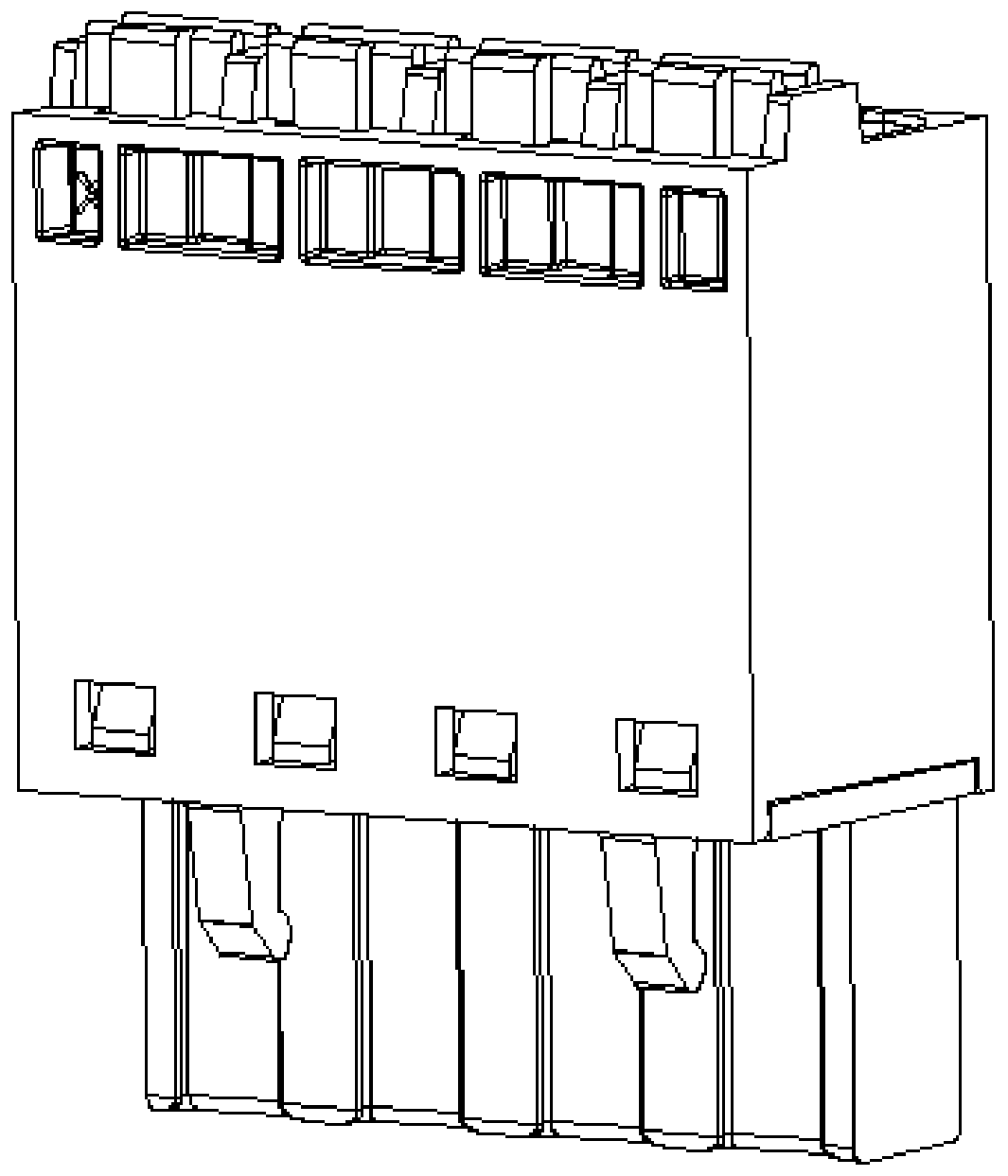
[0048] Embodiment 2: A shrapnel-type internal bridging connection terminal structure, including a second terminal base body 4, the second terminal base body is made of insulating material, and a second clamping component 5 is arranged inside the second terminal base body , the second clamping assembly 5 is composed of a handle 51, an elastic piece 5-2 and a second bridge structure terminal 53, and the handle 51, the elastic piece 52 and the second bridge structure terminal 53 are arranged separately on the second terminal base body 4 Inside, therefore, the handle 51 , the elastic piece 52 and the second bridge structure terminal 53 are separate parts from each other.

[0049] The second bridge structure connection terminal 53 includes a third connection terminal 531, a fourth connection terminal 532 and a second bridge structure 533 arranged symmetrically with the third connection terminal 531, wherein the second bridge structure 533 is a fourth connection of a symmetrical layo...


PUM


Abstract

The invention discloses an internal-bridging connection terminal structure, which comprises a terminal base body and a clamping assembly. The clamping assembly is installed in the terminal base body.The clamping assembly comprises a terminal moving clamping piece, a clamping piece driving device, a bridge structure and wiring terminals. The at least two wiring terminals are fixed in the terminalbase body. The bridge structure enables the wiring terminals to be electrically connected in series. A conductor contact clamping piece is formed at one end of the wiring terminal; a pin type wire clamp capable of clamping a pin type contact is formed at the other end of the wiring terminal; the terminal moving clamping piece can be arranged in the terminal base body in a manner of moving towardsthe conductor contact clamping piece of the wiring terminal; the terminal moving clamping piece and the conductor contact clamping piece of the wiring terminal can clamp a conductor inserted into thewiring terminal; and the clamping piece driving device can drive the terminal moving clamping piece to move in the direction close to or away from the conductor contact clamping piece. When multiple-group parallel wire connection is needed, only one group of wires need to be led out from a power supply, so that multiple-group parallel wire connection can be conveniently carried out according to requirements, and field operation is facilitated.

Description

technical field [0001] The invention relates to the technical field of connectors, in particular to an internal bridging connection terminal structure. Background technique [0002] The clip structure terminal block in the traditional terminal block plug-in connector is a one-in-one-out wiring mode. If this structure needs to realize multiple groups of parallel connection lines, it is necessary to lead multiple wires from the power supply to connect separately, which leads to circuit breakers. Complicated and difficult to apply to multiple wiring modes. Contents of the invention [0003] In order to overcome the above-mentioned defects, the present invention provides an internal bridging connection terminal structure, which is convenient for multiple sets of parallel connection wiring, and the wiring and on-site operation are simple and convenient. [0004] The technical solution adopted by the present invention to solve the technical problem is: an internal bridging conn...

Claims


Application Information

Patent Timeline
IPC IPC(8): H01R13/02H01R13/11H01R4/36
CPCH01R4/36H01R13/02H01R13/111
Inventor 马新博董昌
Owner DINKLE M&E CHINA
Why Eureka
Try Eureka