Pipeline opener

A spreader and pipeline technology, which is applied to hand-held tools, manufacturing tools, etc., can solve the problems of difficulty in removing pipeline components and inconvenient reassembly of pipeline components, so as to improve work efficiency and work quality. , The structure is simple and scientific, the effect of reducing labor intensity

Pending Publication Date: 2018-12-07
ZHEJIANG CHUNHUI INTELLIGENT CONTROL
View PDF5 Cites 0 Cited by
  • Summary
  • Abstract
  • Description
  • Claims
  • Application Information

AI Technical Summary

Problems solved by technology

[0002] In various installation pipelines, due to the existence of pipeline tension, pipeline components can even be clamped between the pipelines on both sides, even if the fittings (such as flange bolts) on the pipeline components are removed, the pipeline The components may not be able to be removed smoothly. Therefore, when the pipeline components need to be repaired and disassembled due to failure, not only the old pipeline components are difficult to remove, but also the replaced pipeline components are also very inconvenient to reinstall. In order to solve this problem, the design Invented a pipe spreader

Method used


Image

  • Pipeline opener
  • Pipeline opener
  • Pipeline opener

Examples


Embodiment Construction

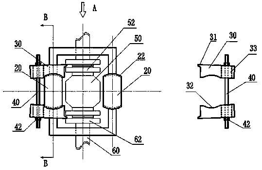
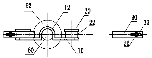
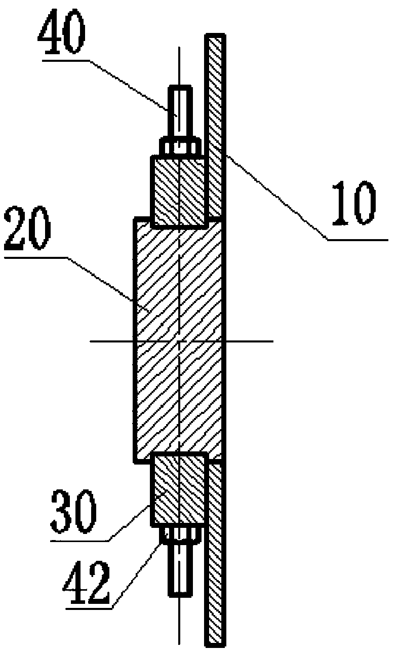
[0014] like figure 1 , figure 2 , image 3 Shown, specific embodiment of the present invention is described as follows:

[0015] A pipeline spreader, which is composed of a bracket 10, four claws 30 and two pull rods 40, and is characterized in that the bracket 10 corresponds to the pipeline 60 on both sides of the pipeline element 50 and is vertically provided with two arc-shaped shoulders 12. Two pivots 20 are set vertically on the other two sides of the bracket 10 corresponding to the pipeline element 50; braces 31 are set on the outside of the top of the brace 30, and a sliding surface 32 is set on the inside of the brace 30 corresponding to the pivot 20, and the tail end of the brace 30 The pull rod through hole 33 is set; the pull rod 40 is provided with threads at least at one end, and the pull rod 40 is screwed with a lock nut 42; the two support claws 30 on the same side are slidingly matched with the corresponding pivot shafts 20, and the brace angles 31 at the fr...


PUM


Abstract

The invention discloses a pipeline opener. The pipeline opener consists of a bracket, opening claws and a pull rod, wherein the positions, which correspond to pipelines at the two sides of a pipelineelement, of the bracket are equipped with two arc-line-shaped shoulders; the positions, which correspond to the rest two sides of the pipeline element, of the bracket are equipped with two pivotal shafts; the outer sides of the top ends of the opening claws are equipped with opening angles; the positions, which corresponds to the pivotal shafts, of the inner sides of the opening claws are equippedwith slide-on curved surfaces, and pull rod through holes are formed in the tail ends of the opening claws; at least one end of the pull rod is equipped with threads, and the pull rod is rotatably matched with a locking nut; the two opening claws at the same side are in sliding fit to the corresponding pivotal shafts; the opening angles at the front ends of the opening claws separately abut against pipeline flange end surfaces at the two sides of the pipeline element; and the tail ends of the opening claws are locked through the pull rod which is in through fit. The pivotal shafts, the shoulders and the bracket are of an integrated structure, and the pivotal shafts and the shoulders are oppositely arranged in pair by taking the pipeline element as the center. The pull rod and the openingclaws are of separate structures, so that a movable assembly that one pull rod is in through fit to the two supporting claws can be pre-assembled, and also can be directly assembled on the site. The positions, which correspond to the slide-on curved surfaces of the opening claws, of the pivotal shafts are equipped with slide slots. The pipeline opener is scientific and reasonable in structure, andis beneficial for replacing the pipeline element.

Description

technical field [0001] The invention relates to the technical field of transmission and distribution pipeline installation, in particular to a pipeline spreader. Background technique [0002] In various installation pipelines, due to the existence of pipeline tension, pipeline components can even be clamped between the pipelines on both sides, even if the fittings (such as flange bolts) on the pipeline components are removed, the pipeline The components may not be able to be removed smoothly. Therefore, when the pipeline components need to be repaired and disassembled due to failure, not only the old pipeline components are difficult to remove, but also the replaced pipeline components are also very inconvenient to reinstall. In order to solve this problem, the design A pipe spreader was invented. Contents of the invention [0003] The object of the present invention is to provide a pipeline maintenance tool, specifically a pipeline spreader, and its technical solution is...

Claims


Application Information

Patent Timeline
IPC IPC(8): B25B27/00
CPCB25B27/00
Inventor 陈镜兔任静梁柏松杨能余玲
Owner ZHEJIANG CHUNHUI INTELLIGENT CONTROL
Why Eureka
Try Eureka