
Rendering optimization method for region division and terminal

A technology of area division and optimization method, which is applied in 3D image processing, image data processing, instruments, etc., can solve problems such as low rendering efficiency, freezing in the rendering process, and large amount of data, so as to avoid freezing and improve rendering efficiency effect

Active Publication Date: 2020-06-26
FUJIAN SHUBO INFORMATION TECH CO LTD
View PDF4 Cites 1 Cited by
  • Summary
  • Abstract
  • Description
  • Claims
  • Application Information

AI Technical Summary

Problems solved by technology

[0002] When rendering the models in the virtual scene, it is generally necessary to obtain the data of all the models in the scene and render all the models. The amount of rendered data is huge, which leads to the phenomenon of stuttering in the rendering process, and the rendering efficiency lower

Method used


Image

  • Rendering optimization method for region division and terminal
  • Rendering optimization method for region division and terminal

Examples


Embodiment 1

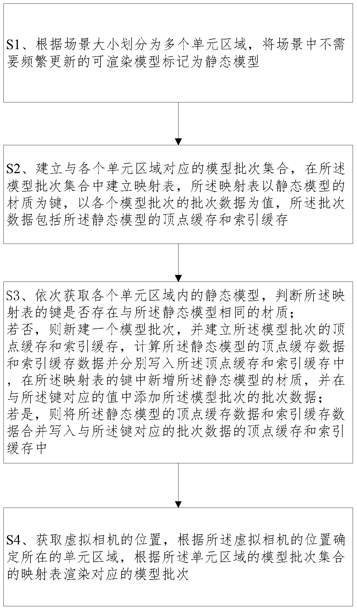
[0072] Please refer to figure 1 As shown, a rendering optimization method for area division, including:

[0073] S1. Divide the scene into multiple unit areas according to the size of the scene, and mark the renderable models in the scene that do not need to be updated frequently as static models;

[0074] Wherein, if the scene is a 3D scene, the 3D scene is divided into x*y*z regions according to the size of the scene, and if it is a 2D scene, the 2D scene is divided into x*y regions. Since the model with bones does not support batch merging, if the model is a model with bones, it will not be marked as a static model.

[0075] When determining the corresponding relationship between each static model and the unit area to which it belongs, the position of the corresponding unit area can be calculated according to the position information of the static model. The calculation method is: first determine the index number of each unit area, if the position of the static model is P...

Embodiment 2

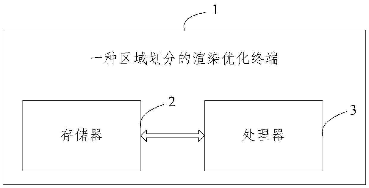
[0095] Please refer to figure 2 , an area-divided rendering optimization terminal 1, including a memory 2, a processor 3, and a computer program stored in the memory 2 and operable on the processor 3, the processor 3 implements the embodiment when executing the computer program One step.

[0096] To sum up, the rendering optimization method and terminal for area division provided by the present invention divide the scene into areas, and divide the static models in each area according to the material to form each model batch. When rendering, as long as Determine the unit area that needs to be rendered, and render each model batch in the model batch set corresponding to the unit area. There is no need to render the entire scene, which avoids the phenomenon of stuttering during the rendering process and improves rendering. efficiency.


PUM


Abstract

The invention relates to a rendering optimization method for region division and a terminal, and the method comprises the steps: dividing a scene into a plurality of unit regions according to the sizeof the scene, and marking a renderable model which does not need to be frequently updated in the scene as a static model; establishing a model batch set corresponding to each unit area, establishinga mapping table in the model batch set, the mapping table taking a material of the static model as a key and taking batch data of each model batch as a value, and the batch data comprising a vertex cache and an index cache of the static model; performing batch combination processing on the static models of the same material, newly building the static models of different materials, then obtaining the position of a virtual camera in the rendering process, determining a unit area where the virtual camera is located according to the position of the virtual camera, and rendering a corresponding model batch according to a mapping table of a model batch set of the unit area. According to the method, during rendering, only the unit area needing to be rendered needs to be determined, all the modelbatches in the model batch set corresponding to the unit area are rendered, and the rendering efficiency is high.

Description

technical field [0001] The invention relates to the field of computer software, in particular to a rendering optimization method for area division and a terminal. Background technique [0002] When rendering the models in the virtual scene, it is generally necessary to obtain the data of all the models in the scene and render all the models. The amount of rendered data is huge, which leads to the phenomenon of stuttering in the rendering process, and the rendering efficiency lower. Contents of the invention [0003] (1) Technical problems to be solved [0004] In order to solve the above-mentioned problems in the prior art, the utility model provides a region division rendering optimization method and a terminal, which can improve rendering efficiency. [0005] (2) Technical solutions [0006] In order to achieve the above object, a technical solution adopted by the present invention is: a rendering optimization method for area division, including: [0007] S1. Divide ...

Claims


Application Information

Patent Timeline
IPC IPC(8): G06T15/00
CPCG06T15/005
Inventor 林进浔黄明炜刘京京陈日清陈国栋
Owner FUJIAN SHUBO INFORMATION TECH CO LTD
Learn More