
A harmonic radar reflector

一种反射器、谐波的技术,应用在无线电波的反射/再辐射、仪器、利用再辐射等方向

Active Publication Date: 2020-06-26
RECCO INVEST
View PDF12 Cites 0 Cited by
  • Summary
  • Abstract
  • Description
  • Claims
  • Application Information

AI Technical Summary

Problems solved by technology

[0008] However, known solutions exhibit problems related to the detection of objects with large differences in size and properties due to the electromagnetic interaction of the object with the reflector

Method used


Image

  • A harmonic radar reflector
  • A harmonic radar reflector
  • A harmonic radar reflector

Examples


Embodiment Construction

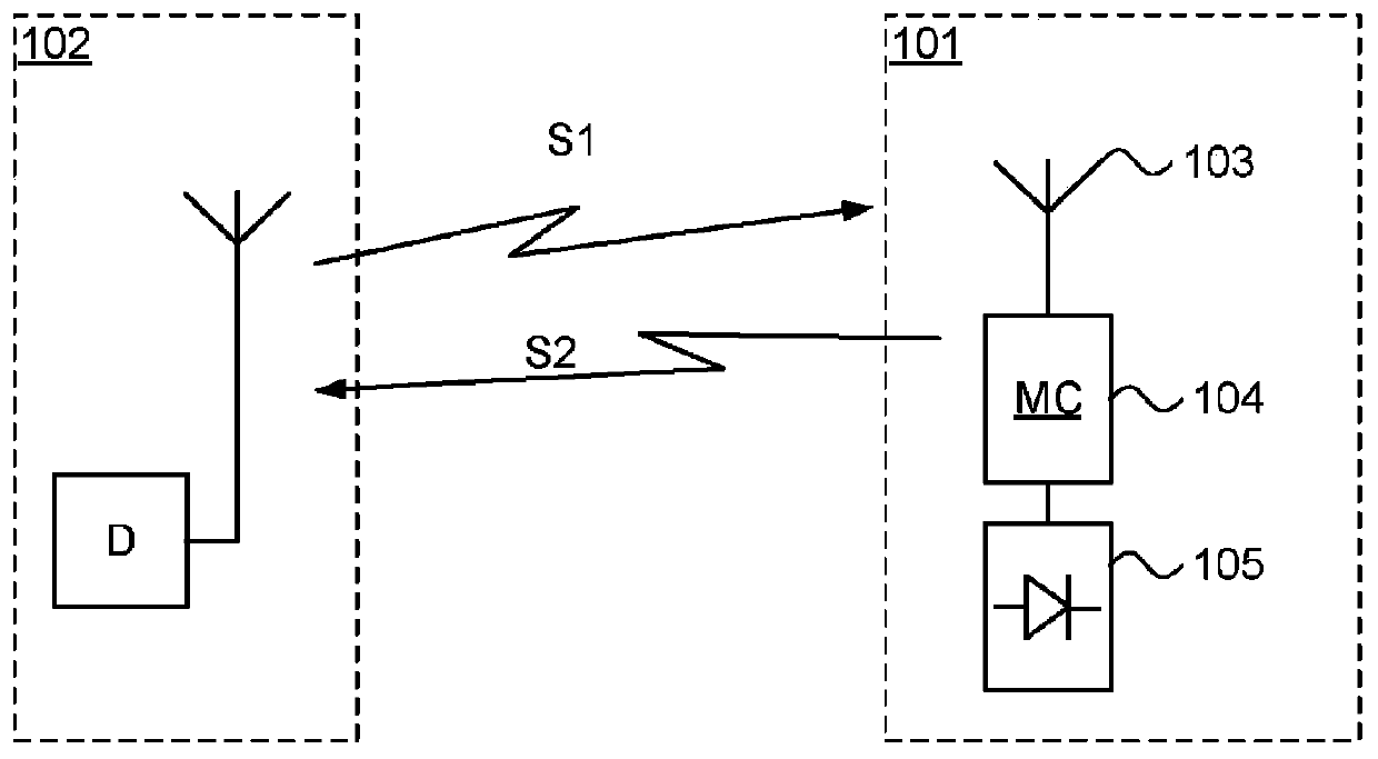
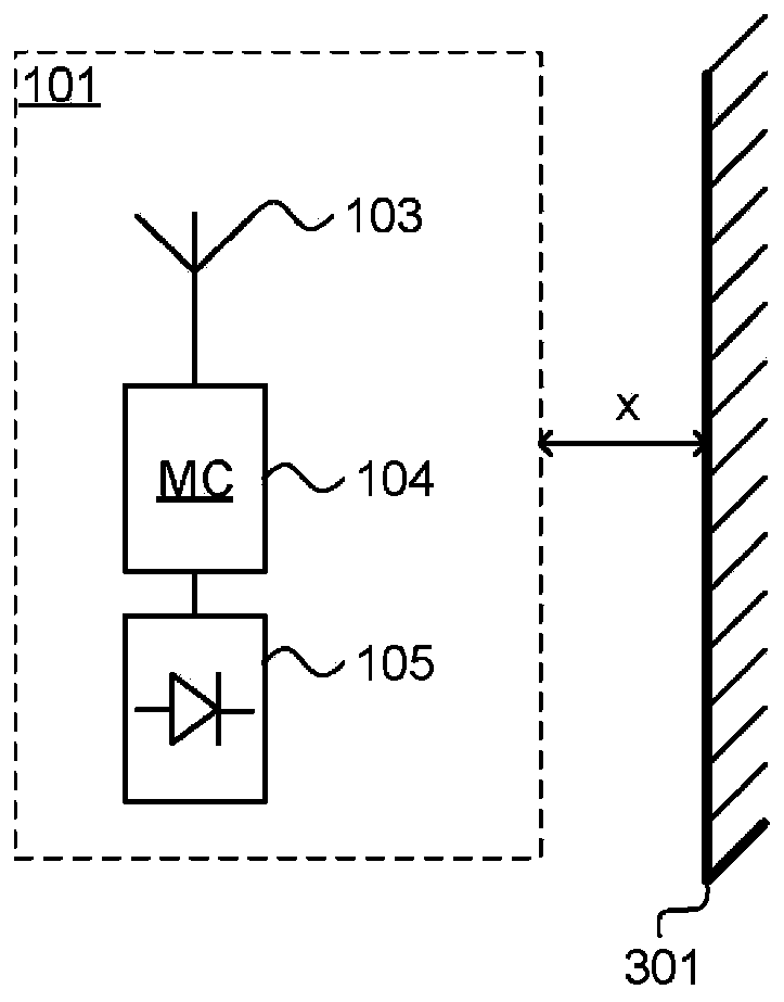
[0027] figure 1 A harmonic reflector circuit, generally designated 101 , and a detector, generally designated 102 , are shown.

[0028] The detector 102 transmits a signal S1 at a frequency fRX, which signal S1 is received by the harmonic reflector circuit 101 and converted by the harmonic reflector circuit 101 into a second signal S2 and transmitted at a frequency fTX. The harmonic reflector circuit 101 receives an input signal S1 through an antenna 103 . The antenna 103 is connected to a matching circuit 104 which provides impedance matching between the antenna 103 and the non-linear circuit 105 for both the frequency fRX and the frequency fTX. Impedance matching is crucial for switching from the first signal S1 to the second signal S2 at their frequencies fRX and fTX respectively with low loss.

[0029] exist figure 2 A typical response from the harmonic reflector 102 is disclosed in . The first curve 201 shows the reflected power P from a signal transmitted at frequen...


PUM


Abstract

A harmonic reflector circuit comprising an antenna connected to a non-linear circuit via a matching circuit, wherein the harmonic reflector circuit is configured to receive a signal at a receive frequency (fRX), and configured to transmit said received signal at a transmit frequency (fTX), where the transmit frequency is a multiple of the receive frequency, the harmonic reflector circuit wherein the receive frequency (fRX) is in an interval from a first frequency to a second frequency, where the first frequency is at least 800 MHz; and the second frequency is at least 34 MHz larger than the first frequency;the received signal is transmitted at the transmit frequency (fTX) with an output power (Pout) of at least 70% of the maximum available output power (Pmax).

Description

technical field [0001] The present invention relates to radar reflectors, and in particular to radar reflectors for harmonic radars. Background technique [0002] Harmonic radar has long been used in search and rescue operations around the world. In a typical avalanche scenario, a skier is lost in an avalanche, rescue teams arrive shortly thereafter, and the skier is equipped with a reflector. The rescue team is equipped with a detector that emits a signal at a transmission frequency, and when the reflector on the skier receives this signal, the reflector converts the frequency of the signal into a multiple of it and emits the signal. This means the detector transmits at a first frequency, receives at multiples of the first frequency, and then uses that information to determine the skier's position. [0003] However, tuning of the reflector involves tuning the antenna to receive at a first frequency and to transmit at multiples of the first frequency. Furthermore, convent...

Claims


Application Information

Patent Timeline
Patent Type & Authority Applications(China)
IPC IPC(8): G01S13/75H04B1/59
CPCG01S13/75G01S13/887A63B29/021H01Q1/2225H01Q15/14H01Q13/16H04B1/59G01S13/758G01S19/19
Inventor 马格纳斯·格兰赫德托马斯·福森
Owner RECCO INVEST
Features
  • Generate Ideas
  • Intellectual Property
  • Life Sciences
  • Materials
  • Tech Scout
  • Unparalleled Data Quality
  • Higher Quality Content
  • 60% Fewer Hallucinations
Learn More