An Intelligent Optical Cable Monitoring System for Optical Cable Protection

A monitoring system and optical cable protection technology, which is applied in the direction of optical instrument testing, machine/structural component testing, optical fiber/optical waveguide equipment testing, etc. It can solve problems such as damage, normal life impact, and failure to notify optical cable maintenance personnel in time. Achieve the effect of high statistical degree and convenient integrated management

Active Publication Date: 2020-11-24
LIUZHOU DADI TELECOMM EQUIP +1
View PDF9 Cites 0 Cited by
  • Summary
  • Abstract
  • Description
  • Claims
  • Application Information

AI Technical Summary

Problems solved by technology

[0002] In recent years, with the development of communication technology, optical fiber communication has become the most mainstream communication method. It has the characteristics of fast communication speed, large communication capacity, good confidentiality performance, and strong adaptability. It is equivalent to other communication methods and has unique characteristics. However, with the rapid development of optical fiber communication networks, more and more optical cables are laid between cities, which makes it more and more difficult to monitor whether the optical cables are damaged. The original traditional monitoring method Mainly using manual means, not only slow but also heavy workload, the cost is very high, can no longer meet the needs of the existing optical cable monitoring, in the face of the increasing data transmission, language communication status, and consumers' increasing demand for communication quality Requirements, how to maintain and monitor the existing huge optical cable network, and how to eliminate cable faults in time has become a problem that researchers pay more and more attention to. Because optical cables are relatively slender and mainly composed of glass, they are easily affected by the external environment. Destruction, the damage rate is relatively high, and due to the long-distance communication requirements, the laying distance is very long, the manual maintenance is difficult and the cycle is long. Once the optical cable is damaged, the entire communication line will be affected. If the fault cannot be handled in time, the wireless Communications and computer networks will be interrupted, which will have a serious impact on the communication industry and the normal life of the people
[0003] However, at present, the optical cable monitoring method is manual monitoring, the degree of automation is not high enough, and it does not have the characteristics of integrated management. It is impossible to realize all-weather, real-time online dynamic monitoring of optical fiber communication. Once a problem occurs, the optical cable maintenance personnel cannot be notified in time. The real-time performance of troubleshooting cannot be achieved, the maintenance efficiency of optical cables is poor, and it is impossible to classify according to the fault situation, and it is impossible to further arrange according to the fault time. It is inconvenient for maintenance personnel to arrange maintenance work according to the damage level. The number of failures of monitoring points in all areas cannot be counted, and the number of failures of monitoring points in different areas cannot be classified and counted. The switching speed of the optical path is not fast enough. The functions of the current monitoring system are still limited to monitoring and alarming. After a problem occurs, maintenance technicians still need to arrive at the scene for maintenance. When the fault occurs in the middle of the night, it will inevitably have a great impact on the maintenance efficiency. The automatic switching between the main line and the backup line cannot be realized, and the communication cannot be guaranteed at all times. Stability needs to be further improved and strengthened; in order to solve the above defects, a solution is now provided

Method used


Image

  • An Intelligent Optical Cable Monitoring System for Optical Cable Protection

Examples


Embodiment Construction

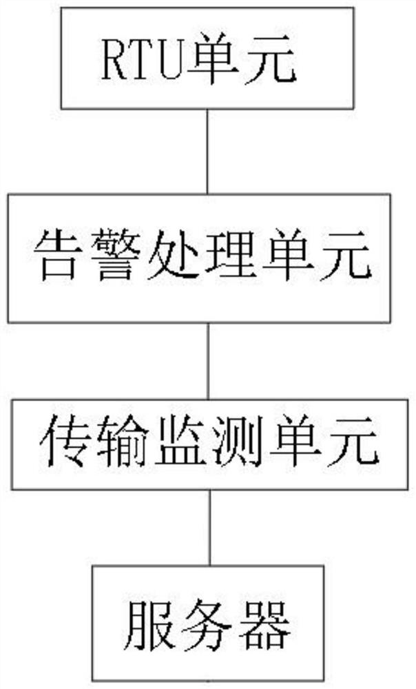
[0064] Such as figure 1 As shown, an intelligent optical cable monitoring system for optical cable protection includes an RTU unit, an alarm processing unit, a transmission monitoring unit, a server, and a retrieval unit;

[0065] Among them, the RTU unit includes an RTU module, an execution module, and a matching switching module. The RTU module is used for terminal detection instruments to collect remote data. The remote data includes optical power data, fault location information, fault time, and monitoring point codes. The execution module is used for Execute the switching of the optical path, the matching switching module is used to retrieve the corresponding backup optical path, and the alarm processing unit is used to perform classification processing according to the fault information. The specific classification processing steps are as follows:

[0066] Step 1: Obtain optical power data, marked as G qin , the optical power damage is divided into three levels, and the...


PUM


Abstract

The invention discloses an intelligent optical cable monitoring system for optical cable protection, which includes an RTU unit, an alarm processing unit, a transmission monitoring unit, a server, and a retrieval unit, wherein the RTU unit includes an RTU module, an execution module, a matching switching module, and an RTU module It is used for terminal detection instruments to collect remote data. The remote data includes optical power data, fault point location information, fault time, and monitoring point codes. The execution module is used to perform optical path switching, and the matching switching module is used to retrieve and match the corresponding backup optical path. The alarm processing unit is used to perform classification processing according to the fault information; the present invention collects remote data through the RTU unit, and performs damage level classification processing on the optical power data through the alarm processing unit, and the server obtains remote data of all monitoring points under abnormal conditions, The automatic collection has a high degree of statistics, which is convenient for integrated management, and can arrange the maintenance sequence according to the level status information of each monitoring point.

Description

technical field [0001] The invention belongs to the field of intelligent distribution, relates to a big data technology, in particular to an intelligent optical cable monitoring system for optical cable protection. Background technique [0002] In recent years, with the development of communication technology, optical fiber communication has become the most mainstream communication method. It has the characteristics of fast communication speed, large communication capacity, good confidentiality performance, and strong adaptability. It is equivalent to other communication methods and has unique characteristics. However, with the rapid development of optical fiber communication networks, more and more optical cables are laid between cities, which makes it more and more difficult to monitor whether the optical cables are damaged. The original traditional monitoring method Mainly using manual means, not only slow but also heavy workload, the cost is very high, can no longer meet...

Claims


Application Information

Patent Timeline
Patent Type & Authority Patents(China)
IPC IPC(8): G02B6/44G01M11/00
CPCG01M11/30G02B6/564
Inventor 黄双揭伦罗琬鈞黄力侯榃洋阳树洪何柏灵
Owner LIUZHOU DADI TELECOMM EQUIP
Why Eureka
Try Eureka