Eureka AIR delivers breakthrough ideas for toughest innovation challenges, trusted by R&D personnel around the world.

Device and method for mounting D bolt in blind cavity of rotating part

A technology for installing devices and rotating parts, applied in the directions of hand-held tools and manufacturing tools, etc., can solve problems such as damage to the stop surface of the rotating part body, damage to the body of the rotating body stop edge, and hidden quality problems, so as to reduce the skill level and solve the problems. The effect of damage to the stop edge and high installation efficiency

Active Publication Date: 2020-07-03
AECC AVIATION POWER CO LTD
View PDF6 Cites 0 Cited by
  • Summary
  • Abstract
  • Description
  • Claims
  • Application Information

AI Technical Summary

Problems solved by technology

[0004] The disadvantages of this method are: (1) Since there is a gap of 0.1-0.5 mm between the stop surface of the D-bolt and the stop surface in the cavity of the rotating part, when installing the self-locking nut on the D-bolt, use a ratchet wrench repeatedly Rotation fastening is likely to cause damage to the stop surface of the rotating body; (2) When installing D-bolts, two people must operate at the same time. One person extends his right hand into the cavity of the rotating body, supports the bottom of the D-bolt with his fingers, and the other uses A socket wrench of the corresponding size tightens the self-locking nut outside the rotating body; (3) When decomposing the D-bolt for engine maintenance, one person often loosens the self-locking nut with a socket wrench outside the rotating body, and the self-locking nut disassembles Moving up, the D-bolt sinks under its own weight, and the stop surface of the D-bolt is separated from the stop surface in the cavity of the rotating part, and cannot be stopped. The operator must lift the D-bolt up to stop it before continuing Decompose the self-locking nut, and repeatedly operate up and down, the motion trajectory of the D-bolt stop side in the rotating body cavity is not straight up and down, the angle is random, and cannot be determined, which will cause the body of the stop side in the rotating body cavity to be stopped by the D-type bolt The edge of the moving side is damaged or even dropped, causing serious quality hazards; and when tightening multiple self-locking nuts at the same time, the efficiency is low, and multiple self-locking nuts are required to be cross-positioned and pre-tightened
(4) During the assembly process of the rotating parts, it may also be disassembled and assembled many times due to the unbalanced balance of the rotating body, which will also cause damage to the body of the rotating body at the stop side. Due to the damage to the body at the stop side, some batches of engines have several Ten units were returned to the factory for repairs, which caused huge economic losses to the country and the company. It is imminent to improve the D-bolt assembly method

Method used


Image

  • Device and method for mounting D bolt in blind cavity of rotating part
  • Device and method for mounting D bolt in blind cavity of rotating part
  • Device and method for mounting D bolt in blind cavity of rotating part

Examples


Embodiment Construction

[0027] The present invention is described in further detail below in conjunction with accompanying drawing:

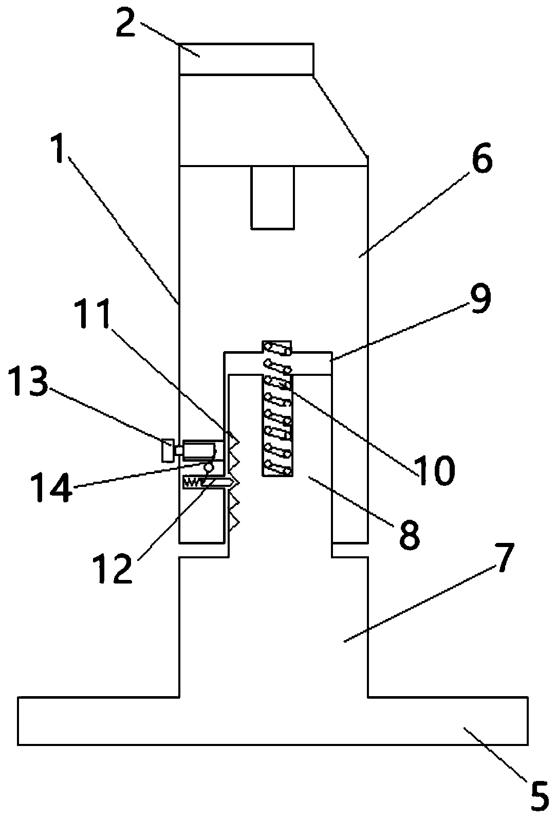
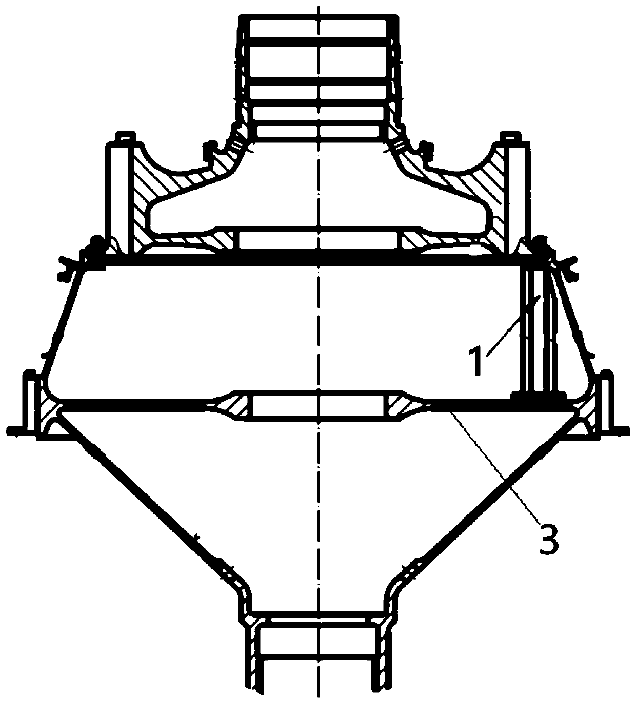
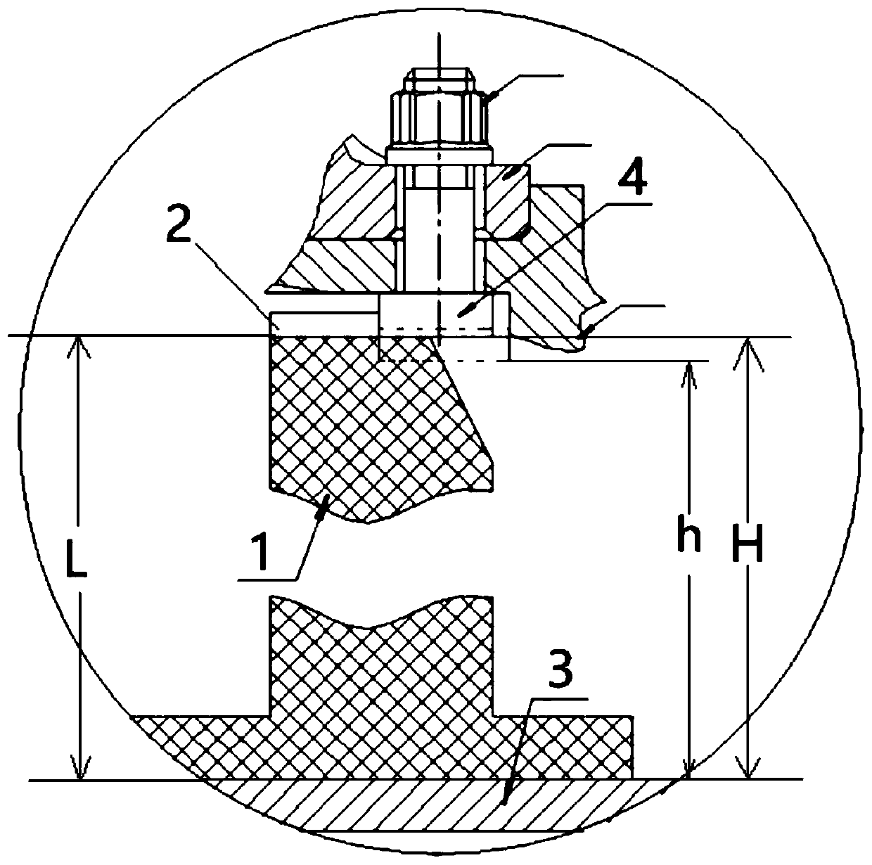
[0028] like Figure 1 to Figure 3 As shown, a D-shaped bolt installation device in the blind cavity of a rotating part includes a support adjustment column 1, and the upper end of the support adjustment column 1 is provided with a rectangular through slot 2, and the width of the rectangular through slot 2 is greater than the length of the straight side of the D-shaped bolt 4. During the process, the height from the bottom of the rectangular through groove 2 of the support adjustment column 1 to the bottom of the support adjustment column 1 is not less than the end surface of the head of the D-bolt 4 to the web plate of the rotating body disc 3 when the minimum contact surface of the D-bolt 4 contacts the stop surface distance;

[0029] Specifically, during the support process, the length from the bottom of the rectangular through groove 2 of the support adjustment col...


PUM


Abstract

The invention discloses a device and method for mounting a D bolt in the blind cavity of a rotating part. The device comprises a support adjustment column, wherein a rectangular through groove is formed in the upper end of the support adjustment column; the width of the rectangular through groove is greater than the length of the straight side of a D bolt; the height between the bottom of the rectangular through groove of the support adjustment column and the bottom of the support adjustment column is not less than the distance between the end face of the head of the D bolt and a rotator bodydisc web when the head of the D bolt is in contact with the minimum contact surface of a motion-stopping surface; and the length between the bottom of the rectangular through groove of the support adjustment column and the bottom of the support adjustment column is less than the distance between the mounting fastening back end face of the D bolt and the rotator disc web. The D bolt is positioned and supported by the support adjustment column with the rectangular adjustment column at the upper end, so that the problems of falling and rotating of the D bolt during mounting and disassembly are solved; the technical problem of damage to the motion-stopping side of a rotator is solved; no particular person is required to support the D bolt; the labor cost is lowered; and the skill level of operating personnel is lowered. The device has the advantages of simple and lightweight structure, reliable positioning, and high economical efficiency.

Description

technical field [0001] The invention belongs to the field of assembly technology of rotating parts or engine maintenance, and in particular relates to a device and method for installing D-shaped bolts in blind cavities of rotating parts. Background technique [0002] Rotating parts play a very important role in engine manufacturing. Both the compressor rotor and the turbine rotor are the key parts of the engine. Most of the compressor rotors are composed of multi-stage disc-drum connections. Good and reliable connections are the key to ensure assembly quality . [0003] The disc-drum connections at all levels of the rotating parts are mostly slit interference and bolt pre-tightening connections, while D-bolts are widely used due to their structural features such as convenient stop, simple connection and small space occupation. Narrow and visually blind. The traditional D-bolt assembly method is to manually put the D-bolt against the stop face in the disc drum cavity, manua...

Claims


Application Information

Patent Timeline
Patent Type & Authority Applications(China)
IPC IPC(8): B25B27/14
CPCB25B27/14
Inventor 王满贤李永民梁影姚世珍李荣杨翠玲蒋南京谢鹏飞
Owner AECC AVIATION POWER CO LTD
Why Eureka
Eureka Blog
Learn More