
Mine car monitoring device and system

A monitoring device and mine car technology, which is applied in the direction of test/monitoring control system, general control system, control/adjustment system, etc., can solve the problem of inaccurate mine car data, wrong diagnosis results, and inability to analyze the use of various parts of the vehicle conditions and other issues to improve diagnostic accuracy and avoid mismatching

Pending Publication Date: 2020-07-03
三一智矿科技有限公司
View PDF0 Cites 2 Cited by
  • Summary
  • Abstract
  • Description
  • Claims
  • Application Information

AI Technical Summary

Problems solved by technology

[0002] In the prior art, in order to diagnose the fault of the vehicle, the vehicle-mounted OBD diagnostic device is usually used to analyze the vehicle and obtain the diagnosis result. The mismatch of the device results in inaccurate data provided by the mine car, resulting in incorrect diagnostic results. In addition, the device only provides diagnostic results, but cannot provide status information of vehicle components, and thus cannot analyze the use of each component of the vehicle. situation

Method used


Image

  • Mine car monitoring device and system
  • Mine car monitoring device and system
  • Mine car monitoring device and system

Examples


Embodiment 1

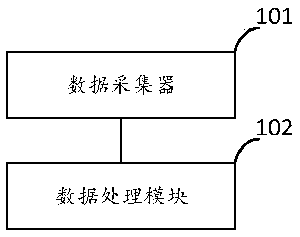
[0037] refer to figure 1 A schematic diagram of a mine car monitoring device is shown, which includes a connected data collector 101 and a data processing module 102 .

[0038] The data collector 101 is used to collect the real-time data of the mine car parts, and sends the real-time data to the data processing module 102, wherein the real-time data includes at least one of the following data of the mine car: lifting times, real-time temperature, pressure and vibration data.

[0039] In a specific implementation manner, the data collector 101 collects real-time data of each component of the mine car, wherein the real-time data may also include the cooling circuit temperature of the mine car in addition to the lifting times, real-time temperature, pressure and vibration data signal, oil rail pressure signal, engine speed signal, vehicle speed signal, cooling fan operation signal and the set controller ERROR status signal, etc., the controller includes such as engine controller...

Embodiment 2

[0062] refer to Figure 4 The schematic diagram of a mining vehicle monitoring system shown includes the mining vehicle monitoring device 401 of the first embodiment, and also includes a control server 402 connected to the mining vehicle monitoring device 401 .

[0063] The control server 402 is used to receive the analysis result uploaded by the mine car monitoring device 401, and generate a mine car maintenance operation instruction corresponding to the analysis result.

[0064] In the above-mentioned system that present embodiment provides, collect the real-time data of mine car parts by setting data collector 101, wherein real-time data includes at least one of following: real-time temperature, number of lifts, pressure and vibration data, and real-time data Send it to the data processing module 102; then the data processing module 102 analyzes the real-time data of the mine car parts in the preset period, and obtains the status information, fault information and maintenan...


PUM


Abstract

The invention provides a mine car monitoring device and system, and relates to the technical field of mine car monitoring. The mine car monitoring device comprises a data collector and a data processing module which are connected with each other, wherein the data collector is used for collecting real-time data (including at least one of the following data of the mine car: the number of lifting times, real-time temperature, pressure and vibration data) of mine car parts, and sending the real-time data to the data processing module; and the data processing module is used for analyzing the real-time data in a preset period to obtain an analysis result (including state information, fault information and maintenance suggestion information of the mine car parts). According to the invention, thefault diagnosis accuracy and management convenience of the mine car can be effectively improved.

Description

technical field [0001] The invention relates to the technical field of mine car monitoring, in particular to a mine car monitoring device and system. Background technique [0002] In the prior art, in order to diagnose the fault of the vehicle, the vehicle-mounted OBD diagnostic device is usually used to analyze the vehicle and obtain the diagnosis result. The mismatch of the device results in inaccurate data provided by the mine car, resulting in incorrect diagnostic results. In addition, the device only provides diagnostic results, but cannot provide status information of vehicle components, and thus cannot analyze the use of each component of the vehicle. situation. Contents of the invention [0003] The purpose of the present invention is to provide a mine car monitoring device and system, which can effectively improve the accuracy of mine car fault diagnosis and the convenience of management. [0004] In a first aspect, the present invention provides a mining vehicl...

Claims


Application Information

Patent Timeline
Patent Type & Authority Applications(China)
IPC IPC(8): G05B23/02
CPCG05B23/0213
Inventor 宋清魁丁守祥田承伟
Owner 三一智矿科技有限公司
Learn More