Supercharge Your Innovation With Domain-Expert AI Agents!

A kind of different direction differential speed rotary extrusion device, extruder and material production method

A technology of extrusion device and rotating center, which is applied in the field of different-direction and differential-speed rotary extrusion devices, can solve the problems of lack of self-adaptive mechanism of melting process, non-existence of mixing relationship, blocking screw channel, etc., so as to improve processing flexibility and strengthen disturbance Function, the effect of stabilizing pressure building ability

Active Publication Date: 2022-04-05
WUYI UNIV
View PDF8 Cites 0 Cited by
  • Summary
  • Abstract
  • Description
  • Claims
  • Application Information

AI Technical Summary

Problems solved by technology

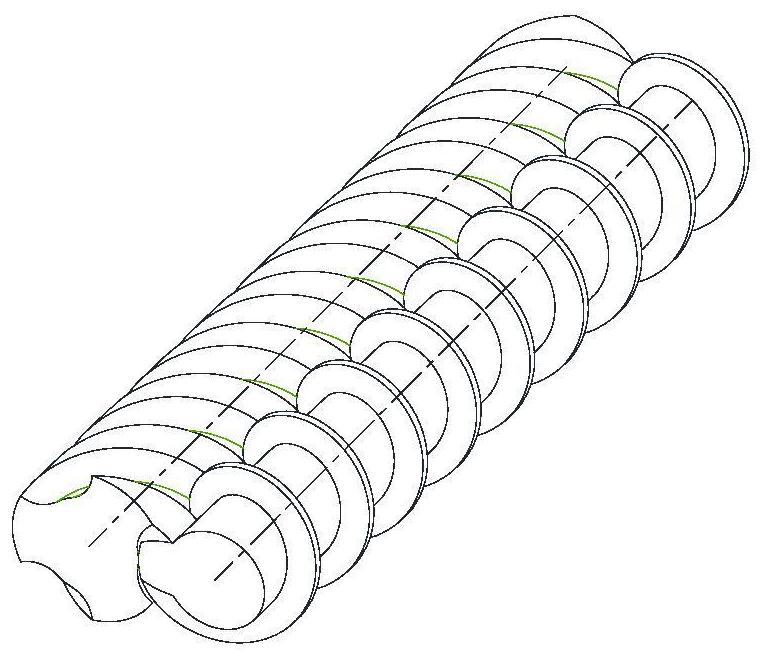
refer to figure 1 , the differential speed counter-rotating twin-screw strengthens the dispersion and mixing effect by introducing a larger speed difference in the meshing area, but the fact that the material is still enclosed in several independent C-shaped chambers has not changed, and the difference between different screws and between the upstream and downstream of the screw There is still no mixing relationship, which results in a limited effect on mixing enhancement
Under such a screw configuration, through the meshing displacement relationship, the C-shaped chamber is pushed from the feed port to the discharge port in the axial direction, and the material is enclosed in the same C-shaped chamber to complete the process of melting, mixing and exhausting. The upstream and downstream lack an adaptive mechanism for the melting process. When the output increases, it is easy to cause unmelted solid materials to block the screw channel, resulting in a significant surge in energy consumption

Method used


Image

  • A kind of different direction differential speed rotary extrusion device, extruder and material production method
  • A kind of different direction differential speed rotary extrusion device, extruder and material production method
  • A kind of different direction differential speed rotary extrusion device, extruder and material production method

Examples


Embodiment Construction

[0049] Embodiments of the present invention are described in detail below, examples of which are shown in the drawings, wherein the same or similar reference numerals designate the same or similar elements or elements having the same or similar functions throughout. The embodiments described below by referring to the figures are exemplary only for explaining the present invention and should not be construed as limiting the present invention.

[0050] In the description of the present invention, if there are descriptions of first, second, third, fourth, etc., it is only for the purpose of distinguishing technical features, and it cannot be understood as indicating or implying relative importance or implicitly indicating the indicated The number of technical features or implicitly indicates the sequence of the indicated technical features.

[0051] In the description of the present invention, unless otherwise clearly defined, terms such as setting and connecting should be unders...


PUM


Abstract

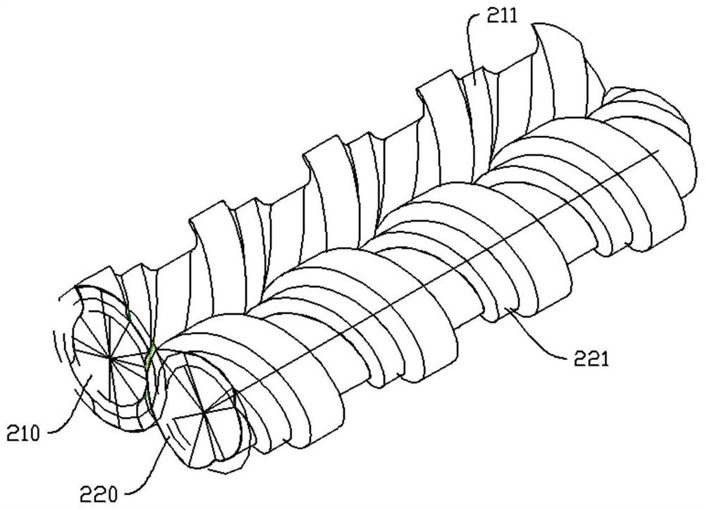
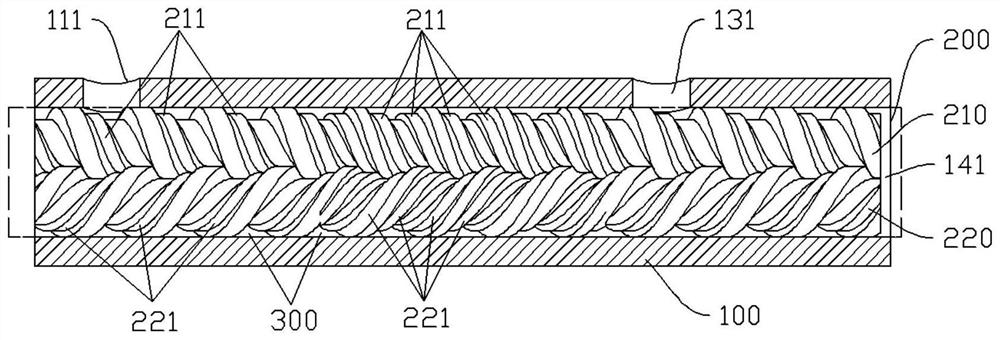
A kind of different direction differential speed rotary extruding device, comprises cylinder and the screw mechanism that is arranged in the cylinder, and screw mechanism comprises first screw and second screw; The root diameter and the top diameter are always meshed with each other; the first screw and the second screw rotate at different speeds at a fixed speed ratio; at least one first intermediate arc structure is arranged between the root diameter and the top diameter of the first screw, A second intermediate arc structure that is always tangent to the first intermediate arc structure is provided between the root diameter and the top diameter of the second screw; the first intermediate arc structure is consistent with the trend of the top diameter and the root diameter of the first screw; The second intermediate arc structure is consistent with the trend of the root diameter and top diameter of the second screw. Through differential rotation in different directions, the self-cleaning of the machining process is realized between the two screws; the original closed C-shaped chamber is expanded into an "8"-shaped chamber through the first intermediate arc structure and the second intermediate arc structure, And it can control the pressure building capacity and extrusion characteristics of the screw structure.

Description

technical field [0001] The invention belongs to the field of multi-screw extruders, and in particular relates to a different-direction differential-speed rotary extrusion device, an extruder and a material production method. Background technique [0002] Co-rotating and counter-rotating multi-screw extruders mainly include a barrel and multiple screws installed in the inner cavity of the barrel. Among them, intermeshing counter-rotating twin-screw extruders are the most widely used counter-rotating multi-screw extruders. The traditional counter-rotating twin-screw extruder adopts the working mode of two screws rotating in opposite directions at the same speed. The material is enclosed in several independent C-shaped chambers and pushed towards the exit direction. It has good pressure building ability, so it is widely used. in the extrusion molding process. [0003] At present, in order to change the mixing and melting efficiency in the meshing zone, a differential twin-scre...

Claims


Application Information

Patent Timeline
Patent Type & Authority Patents(China)
IPC IPC(8): B29C48/41B29C48/425B29C48/525B29C48/575B29C48/505B29C48/68
CPCB29C48/41B29C48/425B29C48/525B29C48/575B29C48/505B29C48/682B29C48/683B29B7/489B29C48/2517B29C48/65B29B7/482B29C48/767B29C48/59B29C48/535
Inventor 徐百平喻慧文肖书平杜遥雪
Owner WUYI UNIV
Features
  • R&D
  • Intellectual Property
  • Life Sciences
  • Materials
  • Tech Scout
  • Unparalleled Data Quality
  • Higher Quality Content
  • 60% Fewer Hallucinations
Learn More