Eureka AIR delivers breakthrough ideas for toughest innovation challenges, trusted by R&D personnel around the world.

Output air outlet section change device and control method thereof

A control method and technology for the air outlet section, which are used in pump control, components of pumping devices for elastic fluids, non-variable-capacity pumps, etc. Restrictions, small air supply range, etc., to meet the air supply needs of multiple people, improve user experience, and reduce high loads

Active Publication Date: 2020-07-17
FOSHAN VIOMI ELECTRICAL TECH +1
View PDF5 Cites 0 Cited by
  • Summary
  • Abstract
  • Description
  • Claims
  • Application Information

AI Technical Summary

Problems solved by technology

[0002] In the hot summer, people usually use fans or air conditioners to cool down in order to get a little coolness in summer. However, most of the conventional tower fans on the market currently have a single direction of wind, and the air supply range is small. In time, the tower fan can automatically shake its head from side to side. Increase the air supply range of the tower fan and change the air supply angle, but because the tower fan is an integral structure, the air supply direction is relatively fixed, and the air supply direction of the tower fan cannot be divided according to the demand, so as to adjust the tower fan. Air supply method, for example, when there are two people in different positions in the room who need to blow air at the same time, the tower fan can only blow air to one person or blow to two people alternately, but cannot blow to two people at different wind directions or speeds at the same time, nor can they blow air at the same time To achieve a variety of blowing forms, therefore, the air supply method of the tower fan is limited, and it cannot meet the needs of multiple people for air supply at the same time

Method used

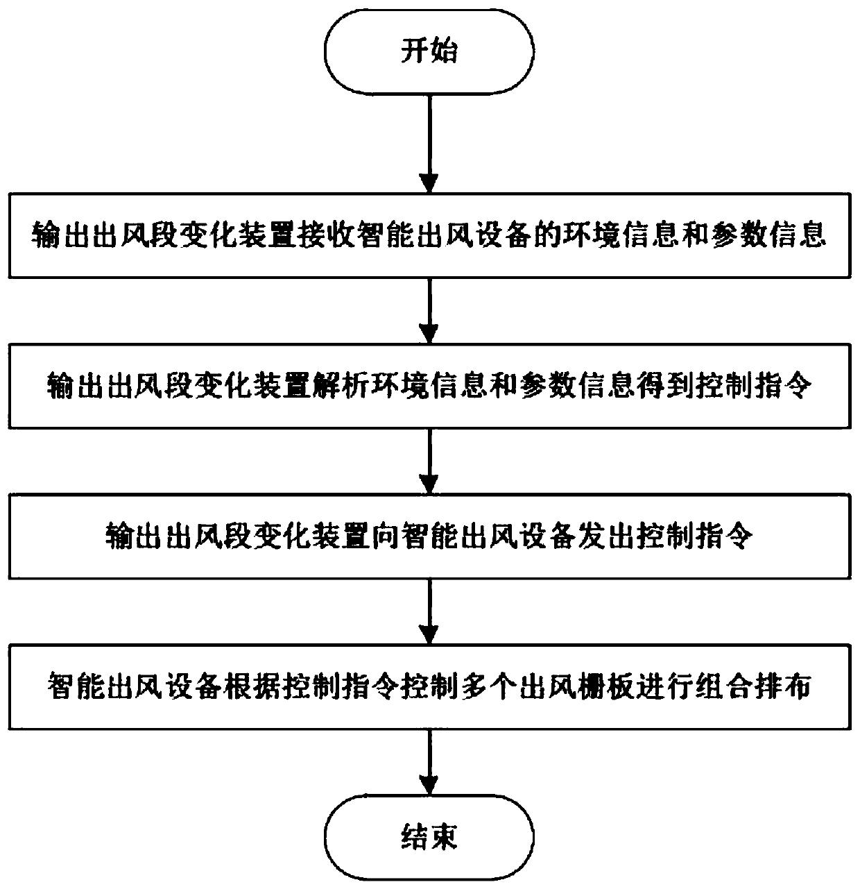
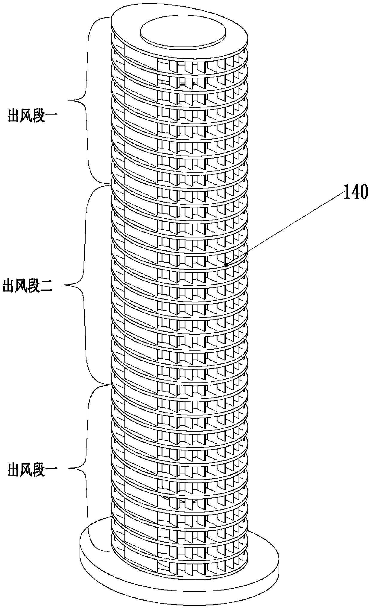
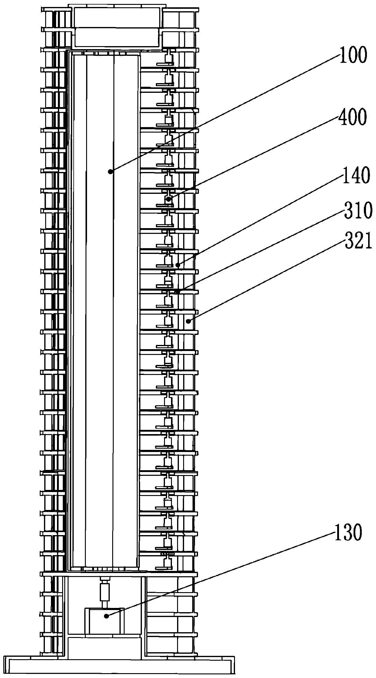

Image

  • Output air outlet section change device and control method thereof
  • Output air outlet section change device and control method thereof
  • Output air outlet section change device and control method thereof

Examples


Embodiment Construction

[0048] The technical solutions of the present invention will be further described below in conjunction with the accompanying drawings and through specific implementation methods.

[0049] In describing the present invention, it is to be understood that the terms "upper", "lower", "left", "right", "vertical", "horizontal", "top", "bottom", "inner", The orientation or positional relationship indicated by "outside" is based on the orientation or positional relationship shown in the drawings, which is only for the convenience of describing the present invention and simplifying the description, rather than indicating or implying that the referred device or element must have a specific orientation, Constructed and operative in a particular orientation and therefore are not to be construed as limitations of the invention.

[0050] A device for changing the output wind section of the present invention, such as figure 2 As shown, it is suitable for an intelligent air outlet system, a...


PUM


Abstract

An output air outlet section change device is suitable for an intelligent air outlet system. The intelligent air outlet system comprises an intelligent air outlet device and the output air outlet section change device. The output air outlet section change device is in communication connection with the intelligent air outlet device. The output air outlet section change device comprises an information receiving module, an information processing module and an instruction sending module. The information receiving module is used for receiving environment information and parameter information sent out by the intelligent air outlet device. The information processing module is used for conducting recognition and analysis according to the environment information and the parameter information to obtain a control instruction of air outlet grid plates of the intelligent air outlet devices. The instruction sending module is used for sending out the control instruction. The invention provides the output air outlet section change device and a control method of the output air outlet section change device. By generating the control instruction for distributing air supply sections of the air outletdevice, the effect of meeting the multi-person air supply requirement at the same time is achieved.

Description

technical field [0001] The invention relates to the technical field of intelligent home appliance control, in particular to a device for changing an output air section and a control method thereof. Background technique [0002] In the hot summer, people usually use fans or air conditioners to cool down in order to get a little coolness in summer. However, most of the conventional tower fans on the market currently have a single direction of wind, and the air supply range is small. In time, the tower fan can automatically shake its head from side to side. Increase the air supply range of the tower fan and change the air supply angle, but because the tower fan is an integral structure, the air supply direction is relatively fixed, and the air supply direction of the tower fan cannot be divided according to the demand, so as to adjust the tower fan. Air supply method, for example, when there are two people in different positions in the room who need to blow air at the same time...

Claims


Application Information

Patent Timeline
Patent Type & Authority Applications(China)
IPC IPC(8): F04D27/00F04D29/70F24F11/30F24F11/64F24F11/61F24F11/70
CPCF04D27/00F04D29/703F24F11/30F24F11/64F24F11/61F24F11/70
Inventor 陈小平唐清生林勇进
Owner FOSHAN VIOMI ELECTRICAL TECH
Why Eureka
Eureka Blog
Learn More