Backlight module and electronic equipment

A technology of backlight module and light-blocking layer, which is applied in branch office equipment, television, optics, etc., can solve the problems of lowering display quality, affecting the performance of backlight module, bad radiation, etc., and achieves the effect of eliminating radiation phenomenon

Active Publication Date: 2020-07-17
ANHUI JINGZHUO OPTICAL DISPLAY TECH CO LTD
View PDF11 Cites 6 Cited by
  • Summary
  • Abstract
  • Description
  • Claims
  • Application Information

AI Technical Summary

Problems solved by technology

There is a hollow column on the iron frame of the backlight module. The inside of the column is used to place the camera. The light enhancement sheet has an ultra-fine prism. When the angles of the prisms of the enhancement film are the same, the problem of poor radiation is likely to occur at the round hole of the column, which will affect the performance of the backlight module and reduce the display quality
[0004] How to design the structure of the backlight module to avoid the problem of poor radiation in the round hole of the column should be the research and development direction of the industry

Method used


Image

  • Backlight module and electronic equipment
  • Backlight module and electronic equipment
  • Backlight module and electronic equipment

Examples


Embodiment Construction

[0035] In order to more clearly illustrate the technical solutions in the embodiment of the present application or the background art, the following will describe the drawings that need to be used in the embodiment of the present application or the background art.

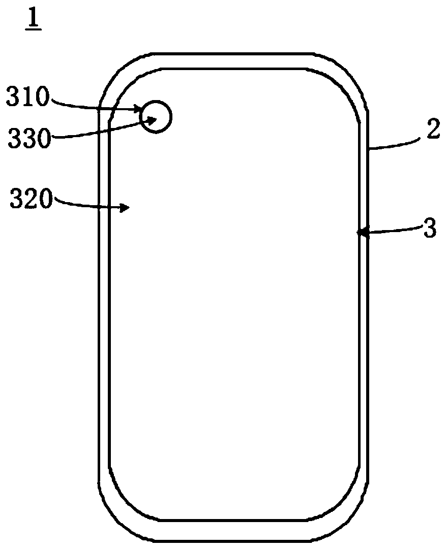
[0036] The present application provides a backlight module and electronic equipment, and the electronic equipment may be mobile terminal equipment such as mobile phones, tablet computers, and notebooks. Such as figure 1 as shown, figure 1 It is a structural schematic diagram of a backlight module applied to a mobile phone. The mobile phone 1 includes a housing 2, a backlight module 3, and a camera (not shown in the figure). The backlight module 3 is located in the housing 2. The backlight module 3 includes an installation area 310 and a light emitting area. 320, the installation area 310 is provided with a through hole 330, and the through hole 330 is used to install the camera. The peripheral area of ​​the backl...


PUM


Abstract

The invention relates to a backlight module. The backlight module comprises an installation area and a light-emitting area. A through hole is formed in the installation area, the through hole is usedfor installing a camera, the light-emitting area surrounds the through hole of the installation area; the light-emitting area comprises a first surface and a second surface which are opposite to eachother, the second surface is a light emitting surface and is used for being attached to a display module; the light emitting surface is the surface of a film layer with a prism structure; the throughhole extends from the first surface to the light emitting surface, a light blocking layer is arranged on the light emitting surface, the light blocking layer is located on the periphery of the throughhole and surrounds the through hole, and the light blocking layer is used for blocking light which is directly reflected to the film layer provided with the prism structure through the peripheral area of the through hole and reaches the light emitting surface. According to the backlight module, the light blocking layer is arranged on the light emitting surface of the backlight module such that light reflected to the light emitting surface through the peripheral area of the through hole of the installation area is blocked, the light cannot be reflected to a visible area, and the situation thata ray phenomenon occurs around the through hole and the use experience of a user is affected is avoided.

Description

technical field [0001] The present application relates to the field of display technology, in particular to a backlight module of an electronic device. Background technique [0002] In recent years, with the popularity of electronic devices such as mobile phones and tablet computers, higher and higher requirements have been put forward for the display quality of display screens. In the production and assembly of a display screen, a backlight module needs to be used to provide a light source for the display module. Therefore, the performance of the backlight module is crucial to the display quality of the display screen. [0003] At present, a backlight module usually includes an iron frame / plastic frame and a reflective sheet, a light guide plate, a diffusion sheet, a brightness enhancement sheet, and a light-shielding glue that are sequentially stacked. There is a hollow column on the iron frame of the backlight module. The inside of the column is used to place the camera....

Claims


Application Information

Patent Timeline
Patent Type & Authority Applications(China)
IPC IPC(8): G02F1/13357G02F1/1333H04N5/225H04M1/02
CPCG02F1/1336G02F1/133606G02F1/133608G02F1/1333H04M1/0264G02F1/133607H04N23/57
Inventor 刘坚
Owner ANHUI JINGZHUO OPTICAL DISPLAY TECH CO LTD
Why Eureka
Try Eureka