
A sensor for monitoring water sediment content

A sediment content and sensor technology, applied in instruments, measuring devices, scientific instruments, etc., can solve the problems of single function, small reflection or scattering probability, difficult control of measurement position and measurement time, etc., and achieve the effect of accurate measurement

Active Publication Date: 2020-09-08
天宇利水信息技术成都有限公司
View PDF23 Cites 1 Cited by
  • Summary
  • Abstract
  • Description
  • Claims
  • Application Information

AI Technical Summary

Problems solved by technology

However, due to the single function, there are many inconveniences in the measurement operation, and there are also deviations in the measurement data; for example, when the sheet-shaped object is facing the test light, the light-receiving surface is relatively large, so there is a high probability of reflection or scattering; When testing light, the light-receiving surface is small, and the probability of reflection or scattering is small; traditional sensors cannot achieve data correction; and when measuring suspended sediment on the river bottom, it is necessary to use auxiliary equipment to lift the floating sand, which is very inconvenient to measure. It is not easy to control the measurement time; the sampling rate cannot be actively adjusted with the water flow velocity or related to the water flow velocity, so it is difficult to know the sediment transport rate of suspended sediment, and it is necessary to cooperate with other auxiliary equipment to adjust the unified flow velocity measurement point and sediment concentration measurement Only the position of the sensor at the point; if foreign matter is attached to the sensor, the existing sensor itself is difficult to handle, and the self-cleaning effect is not ideal

Method used


Image

  • A sensor for monitoring water sediment content
  • A sensor for monitoring water sediment content
  • A sensor for monitoring water sediment content

Examples


Embodiment 1

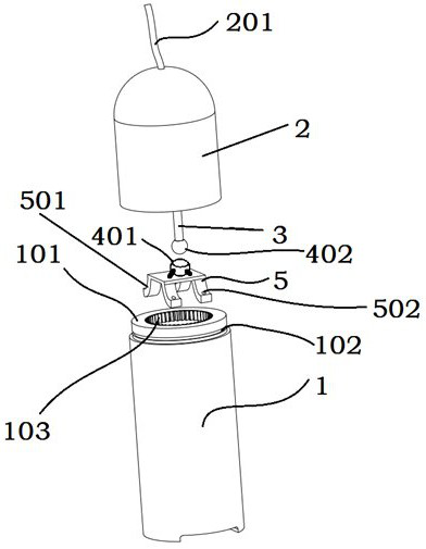
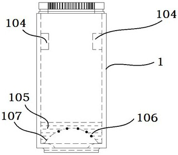
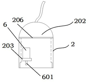
[0035] This embodiment proposes a sensor for monitoring the sediment content in water bodies, such as figure 1 As shown, including the first housing 1 and the second housing 2, the first housing 1 is in the shape of a column as a whole, so as to reduce the collision damage with the outside when rotating, and at the same time, the overall resistance is relatively small; A moving ring 101 is integrally formed on the opening side of the housing 1, which reduces assembly parts, has better sealing performance, is easy to process, and is light in weight; a circumferential groove 102 is provided on the outer wall of the moving ring 101 for assembling an O-ring The inner diameter of the opening side of the second housing 2 matches the outer diameter of the moving ring 101, so as to realize the dynamic sealing after the assembly of the first housing 1 and the second housing 2, and form a closed cavity. When the first housing 1 rotates at a low speed relative to the second housing 2 (fo...


PUM

PropertyMeasurementUnit
wavelengthaaaaaaaaaa

Abstract

The invention provides a sensor for monitoring the water sediment content. The sensor comprises a first housing and a second housing, and the second housing and the first housing are in rotary connection and are in dynamic sealing to form a closed cavity; the first housing is integrally columnar, and one end of the first housing is a light-transmitting U-shaped concave surface; a power supply module, a rotating mechanism, a control unit and an infrared emission unit are arranged in the closed cavity, the control unit is electrically connected with the infrared emission unit so as to control emitted infrared light to be emitted out through the U-shaped concave surface, and the infrared light is scattered or reflected on the surface of an external object to form reflected light; a pluralityof photoelectric sensing units for receiving the reflected light in different directions are arranged in the first housing; the output of each photoelectric sensing unit is connected with the input ofthe control unit; and the rotating mechanism is in transmission connection with the first housing or the second housing so that the first housing and the second housing can rotate relatively. According to the sensor, measurement is more accurate, and the river bottom floating sand condition and suspended load sediment transport rate data can be conveniently measured.

Description

technical field [0001] The invention relates to the technical field of hydrological sand measurement, in particular to a sensor for monitoring the sediment content of a water body. Background technique [0002] At present, the automatic monitoring of river sediment content is a difficult problem in the world. River sediment content has always been a very important indicator in soil and water conservation and hydrological testing. At present, the main sediment monitoring stations in my country still use manual sampling and weighing for analysis. The whole process needs continuous More than half a month, and it will bring very large human errors. When the water level rises and sand needs to be taken, the personnel at the station will take samples regardless of the time at the risk of flooding. Therefore, there is a device that can completely solve the on-line monitoring of sediment to make this tedious and dangerous work simple and efficient. [0003] Existing sensors based o...

Claims


Application Information

Patent Timeline
Patent Type & Authority Patents(China)
IPC IPC(8): G01N15/06G01D21/02
CPCG01D21/02G01N15/06G01N2015/0693
Inventor 吴鉴杨运高旗远
Owner 天宇利水信息技术成都有限公司
Learn More