Light energy acquisition device, PON communication system and light energy acquisition method

A collection device and communication system technology, applied in the field of optical network, to achieve the effect of reducing energy waste

Inactive Publication Date: 2020-07-24
深圳市联洲国际技术有限公司
View PDF4 Cites 0 Cited by
  • Summary
  • Abstract
  • Description
  • Claims
  • Application Information

AI Technical Summary

Problems solved by technology

Then, the signal power of the optical signal arriving at the OUN device will become 3-15-5=-17dbm, and -17dbm still has a large margin relative to the receiving sensitivity of the ONU device-30dbm, that is, there is a large gap in the PON communication system. energy waste
[0005] Therefore, the prior art lacks a solution for collecting the energy margin of the optical signal of the PON communication system so as to utilize the energy margin and reduce energy waste

Method used


Image

  • Light energy acquisition device, PON communication system and light energy acquisition method
  • Light energy acquisition device, PON communication system and light energy acquisition method
  • Light energy acquisition device, PON communication system and light energy acquisition method

Examples


Embodiment 1

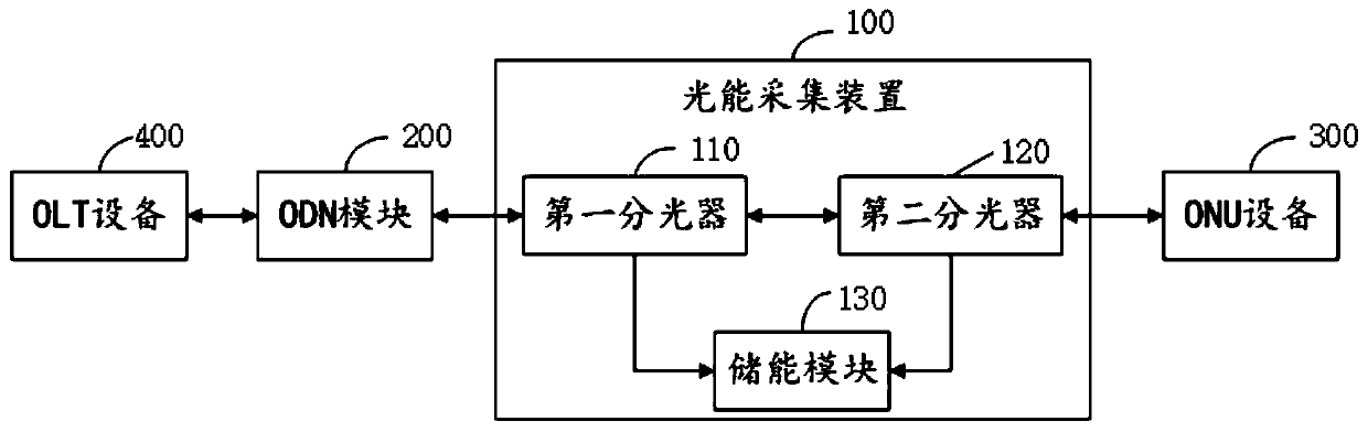
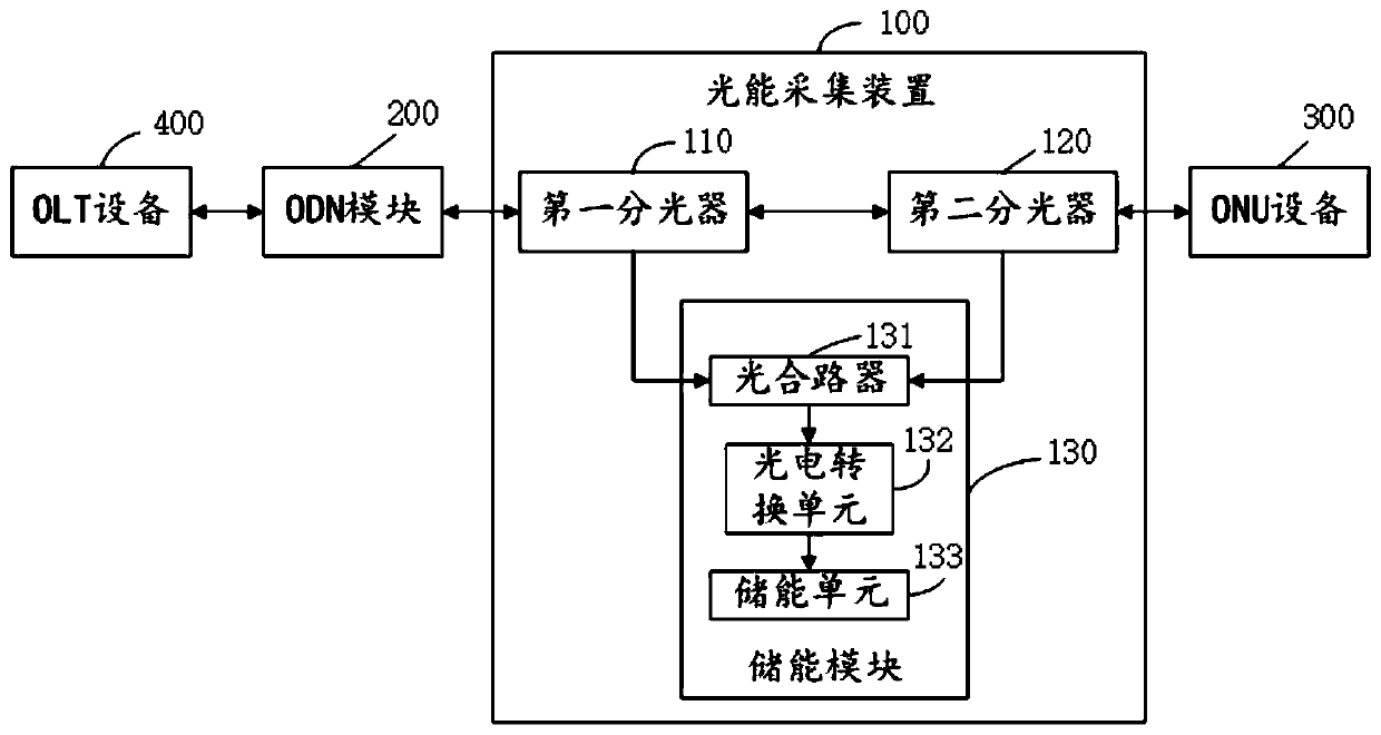
[0040] The invention provides a light energy collection device, please refer to figure 2 , figure 2 It is a structural schematic diagram of the first preferred embodiment of a light energy harvesting device provided by the present invention; specifically, the device 100 is used in a PON communication system, and the device 100 includes a first optical splitter 110, a second optical splitter 120 and energy storage module 130; wherein,

[0041] The uplink interface of the first optical splitter 110 is used to connect with the ODN module 200, the N downlink interfaces of the first optical splitter 110 are correspondingly connected with the N downlink interfaces of the second optical splitter 120, and the first The M downlink interfaces of the optical splitter 110 are correspondingly connected to the M first input terminals of the energy storage module 130;

[0042] The uplink interface of the second optical splitter 120 is used to connect with the ONU device 300, and the K do...

Embodiment 2

[0058] The present invention also provides a PON communication system, please refer to Figure 4 , Figure 4 It is a schematic structural diagram of a preferred embodiment of a PON communication system provided by the present invention; the system includes an OLT device 400, an ODN module 200, P ONU devices 300, and P optical energy collection device 100; wherein,

[0059] The optical signal transmission end of the OLT device 400 is connected to the main line interface of the ODN module 200, and the P branch line interfaces of the ODN module 200 are respectively connected to the first optical splitter 110 of the P optical energy collection device 100. One-to-one corresponding connection of the uplink interface;

[0060] The uplink interfaces of the second optical splitters 120 of the P light energy harvesting devices 100 are respectively connected to the P ONU devices 300 in a one-to-one correspondence.

[0061] During specific implementation, in the PON communication syste...

Embodiment 3

[0071] The present invention also provides a light energy collection method, please refer to Figure 5 , Figure 5 It is a schematic flow chart of a preferred embodiment of a light energy collection method provided by the present invention; specifically, the method is applicable to the light energy collection device provided in Embodiment 1; the method includes:

[0072] S1. The first optical splitter receives the first optical signal transmitted from the OLT device to the ONU device, and distributes the first part of the first optical signal to the second optical splitter, and the second part of the first optical signal The optical signal is distributed to the energy storage module;

[0073] S2. The second optical splitter transmits the first part of the first optical signal to the ONU device;

[0074] S3. The energy storage module collects energy of a second part of the optical signal of the first optical signal.

[0075] Further, the method also includes:

[0076] The s...


PUM


Abstract

The invention discloses a light energy collection device, a PON communication system and a light energy collection method, and the device is used for the PON communication system and comprises a firstoptical splitter, a second optical splitter and an energy storage module. An uplink interface of the first optical splitter is used for being connected with an ODN module, N downlink interfaces of the first optical splitter are correspondingly connected with N downlink interfaces of the second optical splitter, and M downlink interfaces of the first optical splitter are correspondingly connectedwith M first input ends of the energy storage module; an uplink interface of the second optical splitter is used for being connected with ONU equipment, and K downlink interfaces of the second opticalsplitter are correspondingly connected with K second input ends of the energy storage module; wherein N > = 1, M > = 1, and K > = 1. According to the invention, the energy margin of the optical signal transmitted by the PON communication system can be collected, so that energy can be utilized and the energy waste can be reduced.

Description

technical field [0001] The invention relates to the technical field of optical networks, in particular to a light energy collection device, a PON communication system and a light energy collection method. Background technique [0002] With the development of technology, passive optical network communication technology (PON communication technology) is more and more widely used due to its advantages such as long communication distance and large bandwidth. [0003] The PON communication technology corresponds to the ITU-T standard (that is, the International Telecommunication Union standard), and different PON communication systems have corresponding standards to specify the transmission power and reception sensitivity of the system ONU equipment and OLT equipment. For example, GPON communication technology corresponds to the G.984 standard under ITU-T. The G.984 standard stipulates that the transmission power of the ONU equipment under the Class C+ standard is 0.5dbm~5dbm, an...

Claims


Application Information

Patent Timeline
Patent Type & Authority Applications(China)
IPC IPC(8): H04Q11/00
CPCH04Q11/0003H04Q11/0067
Inventor 李伟
Owner 深圳市联洲国际技术有限公司
Why Eureka
Try Eureka