
Liquid crystal panel and liquid crystal display device equipped with same

A liquid crystal panel and display screen technology, applied in the direction of instruments, nonlinear optics, optics, etc., can solve the problems of reduced visual recognition, unsuitability for ordinary liquid crystal display devices, etc., achieve appropriate viewing angle characteristics, and realize viewing angle characteristics Effect

Pending Publication Date: 2020-07-28
MITSUBISHI ELECTRIC CORP
View PDF10 Cites 0 Cited by
  • Summary
  • Abstract
  • Description
  • Claims
  • Application Information

AI Technical Summary

Problems solved by technology

[0012] In addition, the liquid crystal display device as in Patent Document 2 has the following problem: the viewing angle characteristic is improved only when the liquid crystal display device is viewed from an oblique direction, but the visibility in the front direction is reduced, and it is not suitable as a general liquid crystal display device.

Method used


Image

  • Liquid crystal panel and liquid crystal display device equipped with same
  • Liquid crystal panel and liquid crystal display device equipped with same
  • Liquid crystal panel and liquid crystal display device equipped with same

Examples


Embodiment approach 1

[0038] First, the structure of the liquid crystal panel of the liquid crystal display device of the present invention will be described with reference to the drawings. In addition, the drawings are schematic, conceptually illustrating functions and configurations. In addition, this invention is not limited by embodiment shown below. Unless otherwise specified, the basic structure of the liquid crystal panel of the liquid crystal display device is common to all the embodiments. In addition, the part attached|subjected with the same code|symbol is the same or a corresponding part, and this is common throughout the specification.

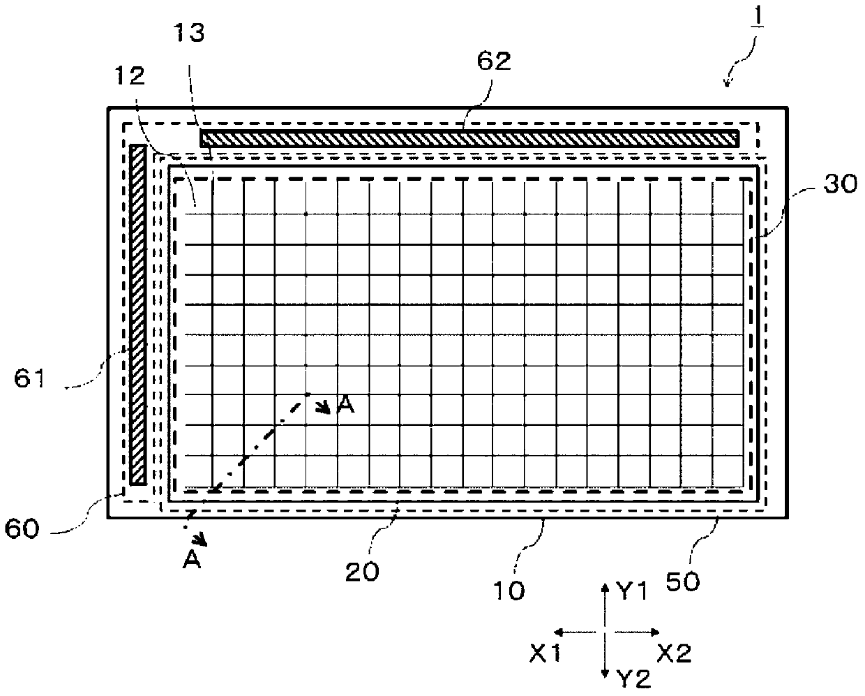
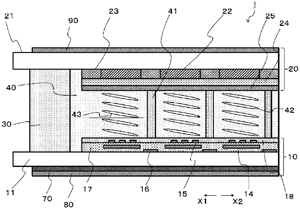
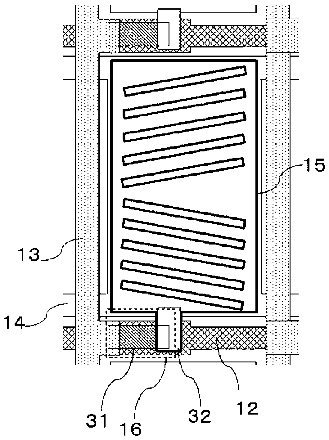
[0039] figure 1 It is a schematic plan view showing the configuration of the liquid crystal panel 1 included in the liquid crystal display device according to Embodiment 1 of the present invention. figure 2 for from figure 1 A schematic cross-sectional view of the liquid crystal panel 1 viewed along the cutting line AA. image 3 To show the figu...

Embodiment approach 2

[0132] In the liquid crystal panel 1 included in the liquid crystal display device according to the second embodiment of the present invention, the pretilt angle 46 of the liquid crystal molecules 45 of the liquid crystal layer 40 is different from that of the first embodiment. Shaft angle θ 1 , the orientation axis angle θ of the liquid crystal molecules 45 2 , the slow axis angle θ of the biaxial retardation film 70 3 , The transmission axis angle θ of the polarizer 80 on the array substrate side 4 Other parts are configured in the same manner as the liquid crystal panel 1 of Embodiment 1 except for the configuration difference.

[0133] Figure 12 for from figure 1 A schematic cross-sectional view of the present embodiment of the liquid crystal panel 1 viewed along the cutting line AA. As mentioned above, the pretilt angle 46 of the liquid crystal molecules 45 in the liquid crystal layer 40 is different from Embodiment 1. The pretilt angle 46 of the liquid crystal mole...


PUM


Abstract

The absorption axis (91) of a polarizing plate (90) provided on an opposing substrate (20) is parallel to the alignment axis (44) of liquid crystal molecules (42, 45) in a liquid crystal layer (40). Abiaxial phase difference film (70) is arranged so that the slow axis (71) of the biaxial phase difference film (70) forms a first angle (theta5) counterclockwise or clockwise from an absorption axis91 or an alignment axis (44) in a liquid crystal panel (1) surface, and so that the transmission axis (81) of a polarizing plate (80) provided on an array substrate (10) forms a second angle (theta6)that is greater than the first angle (theta5) in the same direction as the first angle (theta5) from the absorption axis (91) or the alignment axis (44) in the liquid crystal panel (1) surface.

Description

technical field [0001] The present invention relates to a liquid crystal panel and a liquid crystal display device including the liquid crystal panel. Background technique [0002] A liquid crystal display device having a conventional liquid crystal panel includes: an array substrate having, for example, a plurality of switching elements composed of thin film transistors, pixel electrodes, and common electrodes arranged in a matrix on a transparent substrate; and a color filter substrate arranged as Opposed to the array substrate, it is composed of a transparent substrate provided with color filters; and a liquid crystal panel is sandwiched between the array substrate and the color filter substrate, and has a liquid crystal layer composed of liquid crystal molecules, wherein the Polarizers are respectively arranged on the array substrate and the color filter substrate. [0003] In general, liquid crystal display devices are not only widely used in televisions, computers, an...

Claims


Application Information

Patent Timeline
IPC IPC(8): G02F1/1335G02F1/13363
CPCG02F1/133634G02F2413/12G02F1/133531G02F1/133528G02F1/13363G02F1/1368
Inventor 岩川学岩崎直子藤野俊明玉谷晃清田和司松枝弘宪
Owner MITSUBISHI ELECTRIC CORP
Learn More