
Sliding support hinge for window

A technology for sliding stay hinges and windows, which is applied in the direction of building fastening devices, wing leaf fastening devices, buildings, etc. It can solve the problems of large door and window opening and closing resistance, low load-bearing capacity, easy accumulation of dust and sundries, etc. Achieve the effects of reducing the risk of wear, loosening and falling off, improving load-bearing performance, and large opening angle

Pending Publication Date: 2020-08-04
肇庆巴克菲斯精密五金有限公司
View PDF0 Cites 0 Cited by
  • Summary
  • Abstract
  • Description
  • Claims
  • Application Information

AI Technical Summary

Problems solved by technology

[0003] The problems of this kind of sliding stay hinge are: 1. The chute is open, so the dust-proof effect is poor, and it is easy to accumulate dust and sundries, which is difficult to clean up, resulting in the unsmooth opening and closing of doors and windows; The sliding connection between the rivets in the chute and the frame mounting seat is relatively large, resulting in a large opening and closing resistance of the doors and windows, and after a period of use, the contact between the rivets in the chute and the frame mounting parts is easy to wear and tear. Affect the service life of the hinge; 3. If there is a sliding connection between the cantilever and the frame mounting part, it is necessary to open a long strip-shaped slot on the frame mounting part. The length of the long strip-shaped slot is limited by the size of the door and window frame profile, resulting in The opening angle is limited and can only be opened at a small angle, and this slotting method is not suitable for the application of hinges on narrow frame profiles and profiles with enlarged fan edges, which limits the thickness of each connecting rod and makes the connecting rod thinner , the load-bearing capacity is small, it is easy to cause the sliding stay to close automatically after being stretched, resulting in a short service life of the sliding stay and cannot be used in heavy structures

Method used


Image

  • Sliding support hinge for window
  • Sliding support hinge for window
  • Sliding support hinge for window

Examples


Embodiment Construction

[0020] In order to make the objectives, technical solutions and advantages of the present invention clearer, the technical solutions of the present invention will be described in detail below. Obviously, the described embodiments are only a part of the embodiments of the present invention, rather than all the embodiments. Based on the embodiments of the present invention, all other implementations obtained by a person of ordinary skill in the art without creative work shall fall within the protection scope of the present invention.

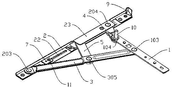
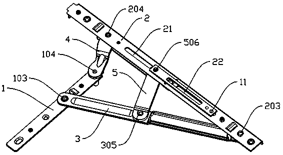
[0021] The purpose of this embodiment is to provide a sliding support hinge for a window, which realizes the opening and closing of the hinge through a rotating structure. Compared with the sliding support in the prior art, the switch is enhanced on the basis of ensuring a large-angle opening. The smoothness, lightness and ease of operation, and improved load-bearing capacity, that is, to avoid the friction between the rivets of sliding hinges for hi...


PUM


Abstract

The invention discloses and provides a sliding support hinge for a window which has a large opening angle and a high bearing capacity. The sliding support hinge for the window comprises a fan mountingpiece (1), a frame mounting piece (2), a cantilever (3), a short connecting rod (4) and a long connecting rod (5), wherein one end of the fan mounting piece (1) is hinged with one end of the short connecting rod (4) through a rivet; the other end of the short connecting rod (4) is hinged with the front end of the frame mounting piece (2) through a rivet; the middle part of the fan mounting piece(1) is hinged with one end of the cantilever (3) through a rivet; the other end of the cantilever (3) is hinged with the rear end of the frame mounting piece (2) through a rivet; and one end of the long connecting rod (5) is hinged with the middle part of the cantilever (3) through a rivet, and the other end of the long connecting rod (5) is in sliding connection with the frame mounting piece (2).The sliding support hinge for the window can be widely applied to the field of door and window hardware.

Description

Technical field [0001] The invention relates to a sliding hinge for windows. Background technique [0002] Hinges usually refer to hinges, and hinges used in doors and windows that can be opened are usually sliding supports, that is, sliding hinges. The sliding hinge in the prior art usually includes a frame mount, a connecting rod, a cantilever and a fan mount to form a four-link mechanism. One end of the link or cantilever is riveted with the fan mount, and the other end is slidably connected with the frame mount. (That is, the rivet is slidably installed in the chute on the frame mounting seat). After installation, the frame mount is installed in the slot of the door and window frame profile, and the fan mount is installed in the slot of the door and window sash profile. [0003] The problems of this sliding hinge are: 1. The sliding groove is open, which has poor dust-proof effect, easy to accumulate dust and debris, and is difficult to clean, resulting in unsmooth opening and...

Claims


Application Information

Patent Timeline
IPC IPC(8): E05C17/32
CPCE05C17/32
Inventor 罗建东
Owner 肇庆巴克菲斯精密五金有限公司
Learn More