Supercharge Your Innovation With Domain-Expert AI Agents!

Self-venting refrigerant coil

A refrigeration system and evaporator coil technology, applied in the field of evaporators, can solve the problems of time-consuming and expensive

Inactive Publication Date: 2020-08-04
CARRIER CORP
View PDF6 Cites 0 Cited by
  • Summary
  • Abstract
  • Description
  • Claims
  • Application Information

AI Technical Summary

Problems solved by technology

[0003] While the potential ignition of leaking, moderately flammable refrigerants can be addressed through various options, such as the provision of safety systems, doing so is costly and time consuming

Method used


Image

  • Self-venting refrigerant coil
  • Self-venting refrigerant coil
  • Self-venting refrigerant coil

Examples


Embodiment Construction

[0030] The detailed description of one or more embodiments of the disclosed apparatus and methods is presented herein by way of example, and not limitation, with reference to the accompanying drawings.

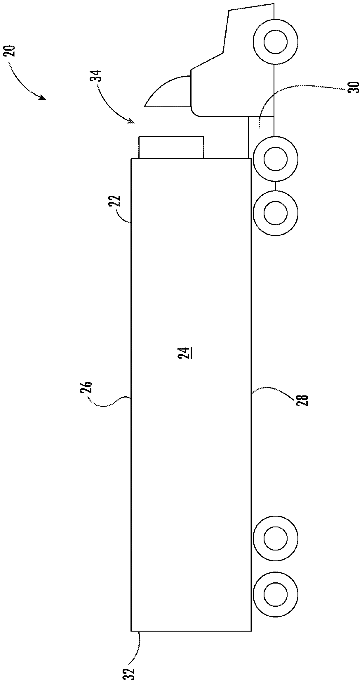
[0031] now refer to figure 1 , illustrates an example of a transport refrigerated trailer 20 for transport of various goods. The trailer 20 has a trailer body 22 that includes an interior "cargo area" 24 formed by thermally insulated walls including a top wall 26, a bottom wall 28, a front wall 30, a rear wall 32, and side walls. wall (not shown). To the extent that cargo within cargo area 24 needs to be kept in an air-conditioned environment, such as where the cargo is, for example, perishable food items, trailer 20 includes refrigeration system 34 . In the illustrated embodiment, the refrigeration system 34 includes a transport refrigeration unit (TRU) attached to a portion of the trailer body 22 , such as the front wall 30 . The TRU is operable to draw heated air from th...


PUM


Abstract

A heat exchanger includes a plurality of tube elements including a first tube segment and a second tube segment and at least one return bend connecting an end of the first tube segment to the second tube segment such that the plurality of tube elements and the at least one return bend define a fluid flow path of the heat exchanger. The at least one return bend is positioned within a cavity isolated from a remainder of the heat exchanger.

Description

Background technique [0001] The following description relates to evaporators, and more particularly to capping arrangements for evaporator coils for certain refrigerants, such as A2L refrigerants. [0002] Regulations in various regions of the world require refrigerant suppliers to reduce the distribution of high global warming potential (GWP) refrigerants. However, this can be problematic because some new blends of low GWP refrigerants, such as A2L refrigerants, are often characterized as being mildly flammable. Therefore, if A2L refrigerant leaks into the interior of the cargo container, for example through the evaporator tubes, the leaking A2L refrigerant can create a risk. [0003] While the potential ignition of leaking, moderately flammable refrigerant can be addressed through various options, such as the provision of safety systems, doing so is costly and time consuming. Contents of the invention [0004] According to an embodiment, a heat exchanger includes: a plur...

Claims


Application Information

Patent Timeline
Patent Type & Authority Applications(China)
IPC IPC(8): F25B39/00F25B41/04F25B45/00F28D7/08F28F9/02F28F9/18F28F11/00F28F17/00B60P3/20F25B41/20
CPCF25B39/00F25B45/00F28D7/082F28F9/02F28F9/18F28F11/00F28F17/005B60P3/20F25B41/20F28F2265/16B60H1/3227F25D11/003F28F1/003F25B2400/12F25B49/005B60H1/3232B60H1/3225B60H1/00014B60H1/00321B60H1/00464B60H1/00485B60H1/3226F28D1/0475
Inventor R.L.小森夫
Owner CARRIER CORP
Features
  • R&D
  • Intellectual Property
  • Life Sciences
  • Materials
  • Tech Scout
  • Unparalleled Data Quality
  • Higher Quality Content
  • 60% Fewer Hallucinations
Learn More