
Electromagnetic attraction type tank body structure

A suction type, tank body technology, applied in the field of electromagnetic suction type tank body structure, can solve the problems of material leakage in the tank, large extrusion force, connection falling off, etc., to improve the use efficiency, realize the internal pressure, and improve the installation efficiency. Effect

Inactive Publication Date: 2020-08-14
王超
View PDF0 Cites 0 Cited by
  • Summary
  • Abstract
  • Description
  • Claims
  • Application Information

AI Technical Summary

Problems solved by technology

[0002] Existing sealed tanks usually use extrusion or interference fit to achieve sealing. Although the sealing effect is obtained, the installation method and operation are more complicated, and in order to achieve higher sealing performance, the extrusion force is usually relatively large. , which makes it difficult to disassemble between the tank body and the sealing cover
[0003] The connection between the tank body and the sealing cover has a change in internal air pressure, which is easy to cause expansion, and then a gap appears, resulting in damage to the sealing performance. Wear and tear, and then cause the connection to fall off, causing the material in the tank to leak
[0004] To this end, an electromagnetic suction tank structure is provided to solve the problems of connection tightness and convenient installation between the tank body and the sealing cover

Method used


Image

  • Electromagnetic attraction type tank body structure
  • Electromagnetic attraction type tank body structure
  • Electromagnetic attraction type tank body structure

Examples


Embodiment Construction

[0028] The following will clearly and completely describe the technical solutions in the embodiments of the present invention with reference to the accompanying drawings in the embodiments of the present invention. Obviously, the described embodiments are only some, not all, embodiments of the present invention. Based on the embodiments of the present invention, all other embodiments obtained by persons of ordinary skill in the art without making creative efforts belong to the protection scope of the present invention.

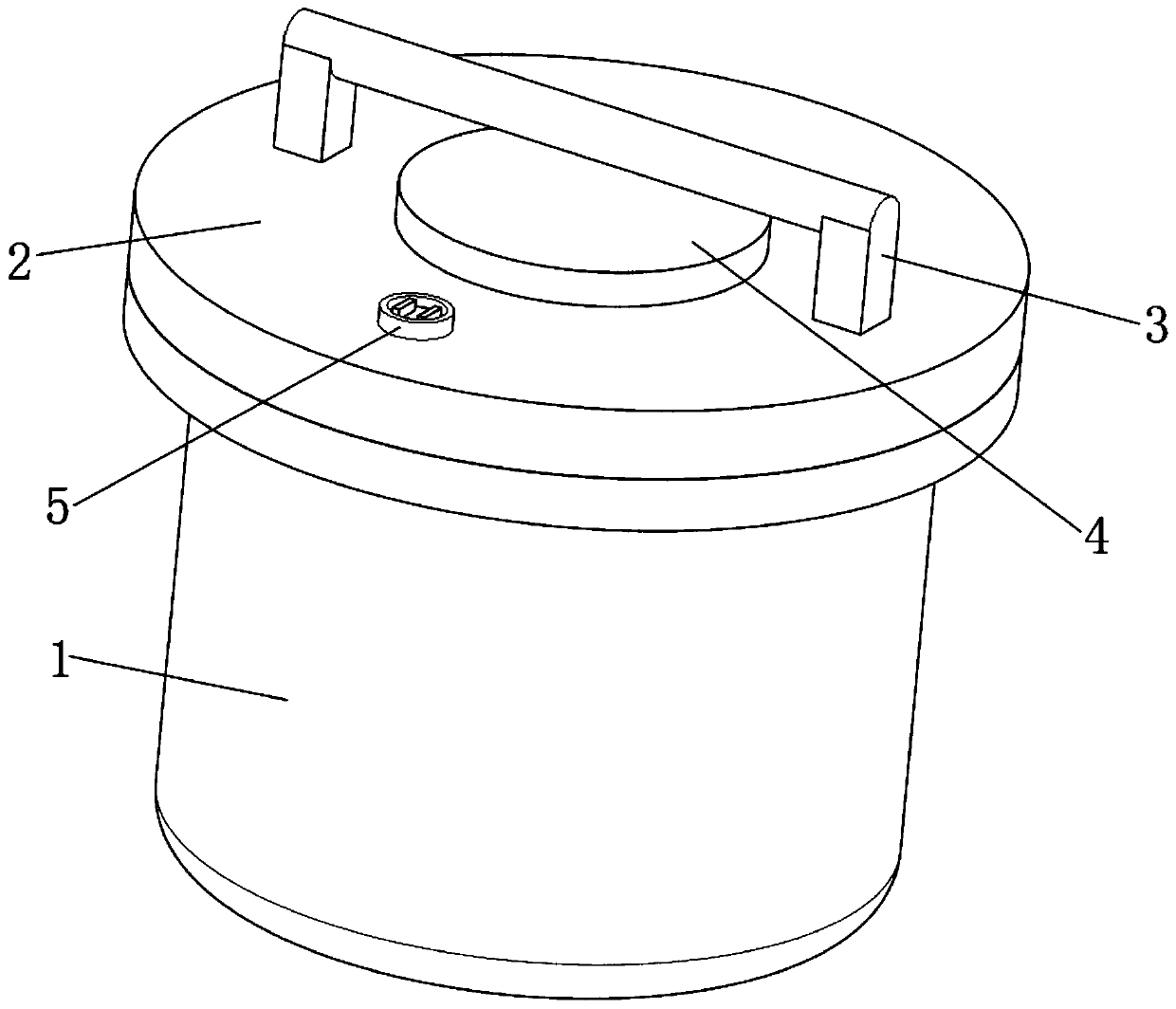
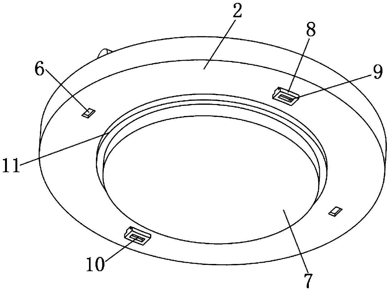
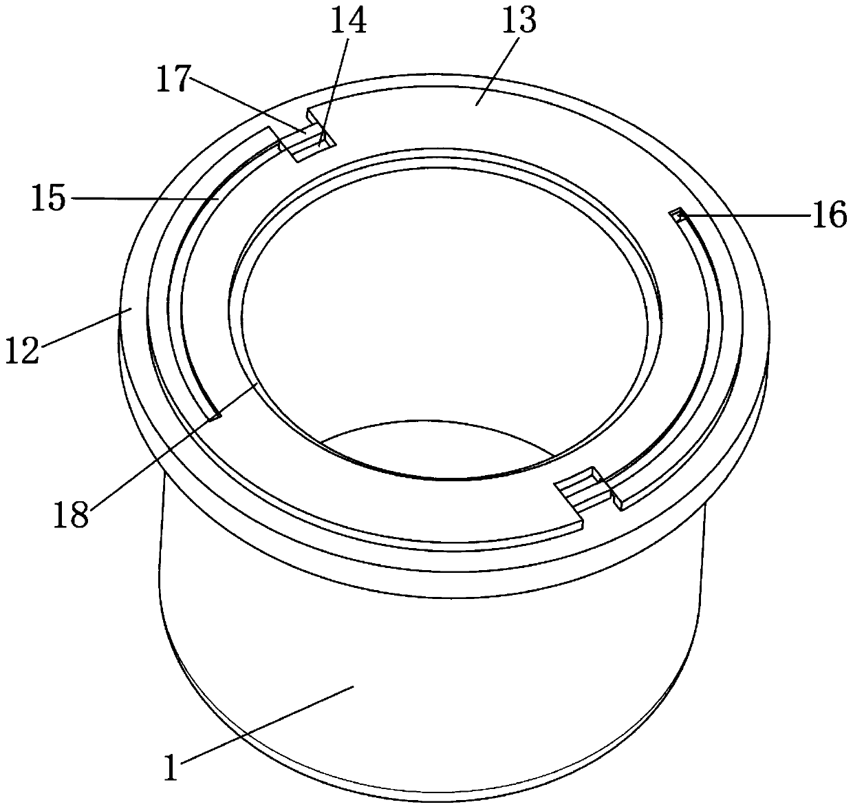
[0029] see Figure 1 to Figure 8 , the present invention provides a technical solution:

[0030] An electromagnetic suction type tank body structure, comprising a tank body 1, a ring-shaped connecting plate 12 is arranged on the outer edge of the upper end surface of the tank body 1, and a sealing cover 2 is arranged on the upper end of the tank body 1.

[0031] The inner wall of the upper end of the tank body 1 is provided with an annular sealing groove 18, ...


PUM


Abstract

The invention relates to the technical field of electromagnetic tank bodies, in particular to an electromagnetic attraction type tank body structure. The electromagnetic attraction type tank body structure comprises a tank body, a circular-ring-shaped connecting plate is arranged on the outer edge of the upper end face of the tank body, a sealing cover arranged at the upper end of the tank body, acircular-ring-shaped sealing groove formed in the inner wall of an inner cavity of the upper end of the tank body, a boss is arranged at the upper end of the connecting plate, and the inner wall of the boss extends to the outer wall of the sealing groove. The electromagnetic attraction type tank body structure has the beneficial effects that an arc-shaped sliding groove is arranged to be in running fit with a sliding block, so that rotating installation between the sealing cover and the tank body is achieved, threaded connection of multiple times of rotation is replaced, the installation efficiency is improved, abrasion is reduced, and the use efficiency is improved; by arranging electromagnetic adsorption to be cooperation with lifting of a U-shaped pipe, adsorption and fixation of an electromagnetic piece and a lifting block are achieved, and the connection sealing performance is greatly improved; and meanwhile, by arranging a groove, staggered inserting connection between the lifting block and the arc-shaped sliding groove is achieved, so that rotation of the sealing cover is avoided, and meanwhile buffering of internal air pressure is achieved.

Description

technical field [0001] The invention relates to the technical field of electromagnetic tanks, in particular to an electromagnetic suction tank structure. Background technique [0002] Existing sealed tanks usually use extrusion or interference fit to achieve sealing. Although the sealing effect is obtained, the installation method and operation are more complicated, and in order to achieve higher sealing performance, the extrusion force is usually relatively large. , thus making it difficult to disassemble between the tank body and the sealing cover. [0003] The connection between the tank body and the sealing cover has a change in internal air pressure, which is easy to cause expansion, and then a gap appears, resulting in damage to the sealing performance. Wear and tear, and then cause the connection to fall off, causing the material in the tank to leak. [0004] Therefore, an electromagnetic suction type tank body structure is provided to solve the problems of connecti...

Claims


Application Information

Patent Timeline
IPC IPC(8): B65D53/02B65D55/02
CPCB65D53/02B65D55/02B65D2251/20
Inventor 王超
Owner 王超
Learn More