
Automatic machining equipment for steel hot-rolling manufacturing forming

A processing equipment and steel technology, applied in the field of steel manufacturing and forming, can solve the problems affecting the smoothness of the steel surface, affecting the bending treatment of steel, and damage to the bending place, so as to reduce deformation damage, save manpower and material resources, and reduce relative friction. Effect

Active Publication Date: 2020-08-18
广东习创实业发展有限公司
View PDF4 Cites 4 Cited by
  • Summary
  • Abstract
  • Description
  • Claims
  • Application Information

AI Technical Summary

Problems solved by technology

[0005] The invention can solve the problem that the traditional steel manufacturing and forming equipment usually directly bends the steel due to a large angle change in a short period of time, which will cause damage to the bending part, and because the steel to be processed is generally long After bending, there will be irregular deformation between the bent part and the unbent part, which will affect the next bending process of the steel. Since the bent plate is usually in direct contact with the steel, during the bending process, the bent plate and the steel will be separated. Friction occurs, affecting the smoothness of the steel surface and other problems

Method used


Image

  • Automatic machining equipment for steel hot-rolling manufacturing forming
  • Automatic machining equipment for steel hot-rolling manufacturing forming
  • Automatic machining equipment for steel hot-rolling manufacturing forming

Examples


Embodiment Construction

[0029] The embodiments of the present invention will be described in detail below with reference to the accompanying drawings, but the present invention can be implemented in many different ways defined and covered by the claims.

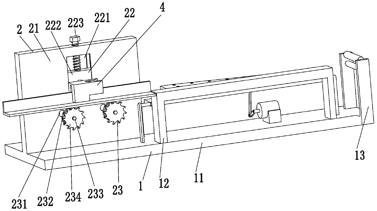
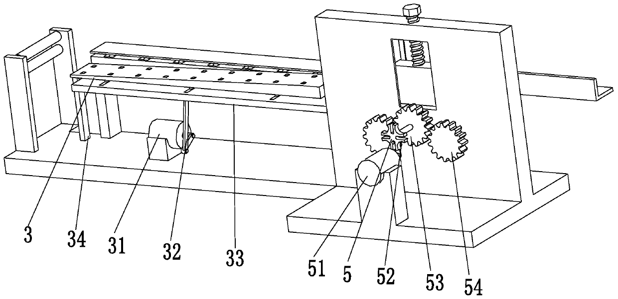
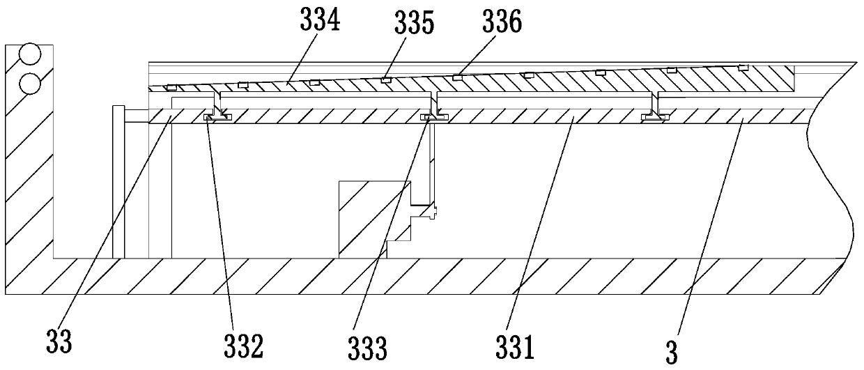
[0030] Such as Figure 1 to Figure 4 As shown, an automatic processing equipment for hot-rolled steel manufacturing and forming includes a fixed base 1, an installation base 2, a bending device 3, a molding device 4, and an intermittent transmission device 5. The left end of the fixed base 1 is equipped with an installation base 2. A bending device 3 is installed on the right end of the fixed base 1, a molding device 4 is installed on the front side of the upper end of the installation base 2, and an intermittent transmission device 5 is installed on the rear side of the upper end of the installation base 2; wherein:

[0031] The fixed base 1 includes a bottom fixed plate 11, a feed limit frame 12, and a clearing mechanism 13. The right end of the b...


PUM


Abstract

The invention relates to automatic machining equipment for steel hot-rolling manufacturing forming. The automatic machining equipment comprises a fixed base, a mounting base, a bending device, a shaping device and an intermittent transmission device, wherein the mounting base is mounted at the left end of the fixed base, the bending device is mounted at the right end of the fixed base, the shapingdevice is mounted on the front side of the upper end of the mounting base, and an intermittent transmission device is mounted on the rear side of the upper end of the mounting base. The automatic machining equipment can solve the following problems that in the process that traditional steel manufacturing and forming equipment directly bends steel generally, due to the fact that large-amplitude angle changes occur in a short time, the bent position can be damaged, due to the fact that the steel to be treated is generally long, irregular deformation can occur at the bent position and the non-bent position after bending, and the next bending treatment of the steel is influenced; and due to the fact that a bending plate is usually in direct contact with the steel, in the bending process, thebending plate can rub against the steel, and the smoothness of the surface of the steel is affected.

Description

technical field [0001] The invention relates to the technical field of steel material manufacturing and forming, in particular to an automatic processing equipment for steel material hot rolling manufacturing and forming. Background technique [0002] Steel is a material of a certain shape, size and performance made of steel ingots, billets or steel through pressure processing. Most steel processing is through pressure processing, which causes plastic deformation of the processed steel. Steel is an essential and important material for national construction and the realization of the four modernizations. It is widely used and has a variety of varieties. According to the different cross-sectional shapes, steel is generally divided into four categories: profiles, plates, pipes and metal products. Steel generally needs to be processed into specific shapes and used in different places. [0003] At present, there are usually the following defects in the hot-rolled manufacturing ...

Claims


Application Information

Patent Timeline
Patent Type & Authority Applications(China)
IPC IPC(8): B21D31/00B21D43/08F16F15/067F16F15/02
CPCB21D31/005B21D43/08F16F15/067F16F15/02
Inventor 蔡普忙
Owner 广东习创实业发展有限公司
Learn More