DCC acquisition method, focusing method and system, camera module and terminal
A technology of a camera module and an acquisition method, applied in the field of photography, can solve problems such as out-of-focus, affecting the user's applicable experience, etc.
- Summary
- Abstract
- Description
- Claims
- Application Information
AI Technical Summary
Problems solved by technology
Method used
Image
Examples
Embodiment 1
[0103] Considering that under different light sources and distances, the DCC value in the camera module will also be different, as shown in the following table:
[0104]
[0105] The above table is the result taken by the Shield PD module. The background image uses ISO-12233chart (resolution test target board), and the standard D65 light source is used in the Samsung laboratory test, and the data in the above table are DCC at the center of the image Round the value, the DCC at the center of the image that comes with the module is rounded to 24.
[0106] It can be seen from the table that for the same module, under the same light source, the DCC will change at different distances; at the same distance, the DCC will also change under different light sources. In this embodiment, the DCC can be effectively and dynamically adjusted to ensure the focusing accuracy of the PDAF focusing mode, specifically:
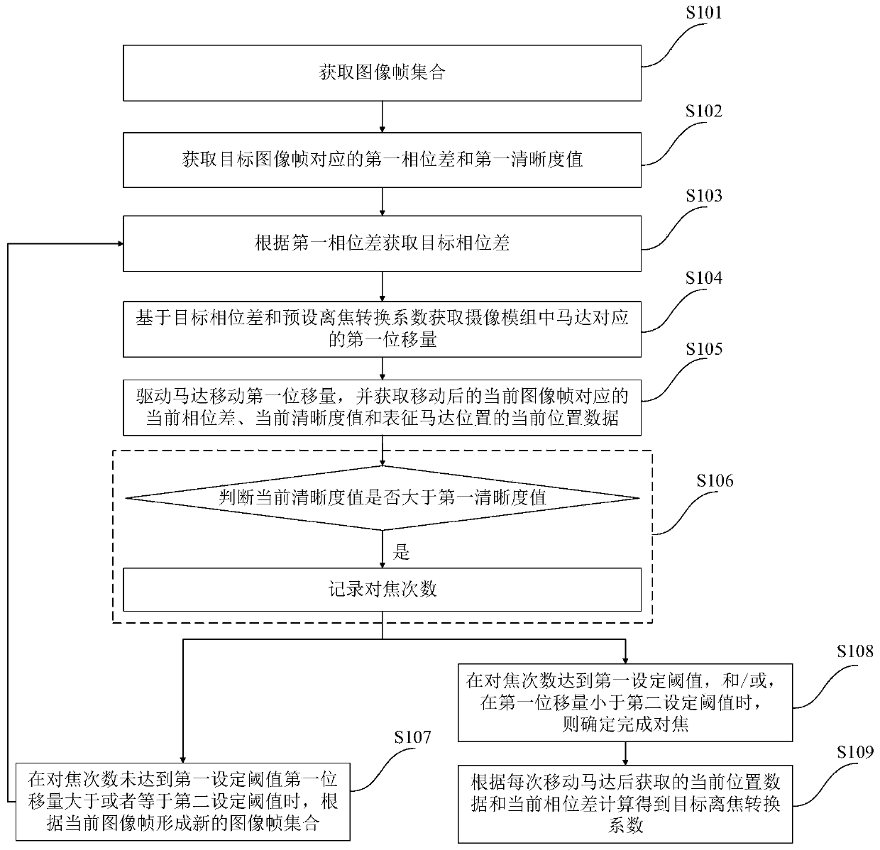
[0107] Such as figure 1 As shown, the method for obtaining the defocus c...
Embodiment 2
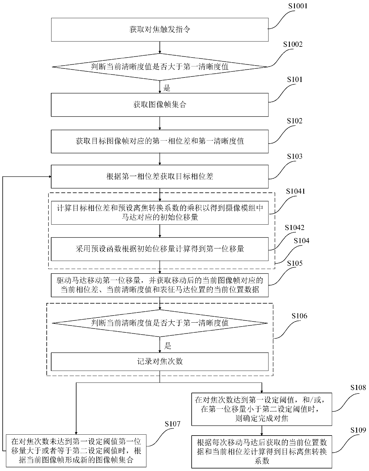
[0120] Such as figure 2 As shown, the acquisition method of the defocus conversion coefficient in the camera module of this embodiment is a further improvement on Embodiment 1, specifically:
[0121] Before step S101, it also includes:
[0122] S1001. Obtain a focus trigger instruction;
[0123] S1002. Determine whether the focus trigger instruction satisfies a preset condition, if yes, execute step S101; if not, determine to use the CDAF focusing method for focusing.
[0124] Wherein, the preset conditions include but are not limited to that the phase difference satisfies the first set condition, the confidence level corresponding to the phase difference satisfies the second set condition, the brightness of the current scene satisfies the third set condition, and so on. The preset condition can also be flexibly adjusted according to actual conditions.
[0125] Also include before step S103:
[0126] Acquiring the first degree of confidence corresponding to the first phas...
Embodiment 3
[0176] Such as Figure 4 As shown, the focusing method of the camera module in this embodiment is realized by the acquisition method of the defocus conversion coefficient in the camera module in Embodiment 1 or 2.
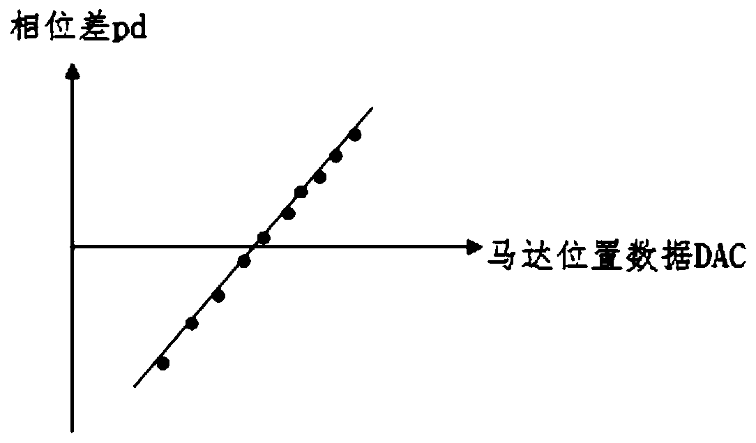
[0177] When the target defocus conversion coefficient and intercept parameters of the target straight line are obtained according to the current position data and the current phase difference obtained after each movement of the motor, the focusing method of this embodiment includes:
[0178] S201. Calculate and obtain the target displacement amount corresponding to the motor according to the target defocus conversion coefficient and the intercept parameter;
[0179] S202. Drive the motor to move the target displacement amount to focus.
[0180] In this embodiment, based on adaptively recalculating the new DCC during the focusing process, the corresponding displacement of the motor is calculated, and then the focus is performed according to the displacement, which ...
PUM
 Abstract
Description
Claims
Application Information
 - R&D
- Intellectual Property
- Life Sciences
- Materials
- Tech Scout
- Unparalleled Data Quality
- Higher Quality Content
- 60% Fewer Hallucinations
Browse by: Latest US Patents, China's latest patents, Technical Efficacy Thesaurus, Application Domain, Technology Topic, Popular Technical Reports.
© 2025 PatSnap. All rights reserved.Legal|Privacy policy|Modern Slavery Act Transparency Statement|Sitemap|About US| Contact US: help@patsnap.com


