Wired signal receiving device

A technology for receiving devices and wired signals, which is applied to baseband system components, multiple input and output pulse circuits, etc., and can solve problems such as loss of timing margins and failure of the wired signal transmitter 110 to operate normally.

Inactive Publication Date: 2010-02-17
NOVATEK MICROELECTRONICS CORP
View PDF0 Cites 0 Cited by
  • Summary
  • Abstract
  • Description
  • Claims
  • Application Information

AI Technical Summary

Problems solved by technology

At this time, the signal transmitting device 110 will lose some so-called timing margins, causing the duty cycle of the output signal RX_OUT to not be 50%, which in turn causes the wired signal transmitting device 110 to transmit at high frequencies. not working properly

Method used


Image

  • Wired signal receiving device
  • Wired signal receiving device
  • Wired signal receiving device

Examples


Embodiment Construction

[0073] In the following, a number of embodiments of the solar power generation device of the present invention will be provided for description, accompanied by diagrams, so that those of ordinary skill in the art can better understand and implement them accordingly.

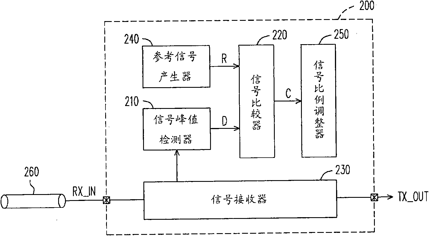
[0074] Please refer to figure 2 , figure 2 A schematic diagram showing the first embodiment of the wired signal receiving device of the present invention. The wired signal receiving device 200 includes a signal peak detector 210, a signal comparator 220, a signal receiver 230, a reference signal generator 240, and a signal ratio adjuster 250. The wired signal receiving device 200 receives the transmission signal RX_IN by connecting the transmission line 260.

[0075] The signal receiver 230 is coupled to the transmission line 260 and receives the transmission signal RX_IN transmitted by the transmission line 260. The signal receiver 230 determines the logic level TX_OUT of the transmission signal RX_IN according to...


PUM


Abstract

The invention relates to a wired signal receiving device, which comprises a signal receiver, a signal peak detector and a signal comparator. The signal receiver comprises an operation current detection circuit and is used for detecting an operation current. The signal receiver also receives a transmission signal. The signal peak detector receives the operation current and is used for detecting the peak of the operation current so as to generate a peak current. The signal comparator generates an output current by comparing a reference signal and the peak current, and further adjusts the operation current.

Description

Technical field [0001] The invention relates to a wired signal transmission device. Background technique [0002] With the progress of society, the transmission of information has become a very important part of people's lives. The wired signal transmission technology is the longest and most mature technology used by people. Compared with wireless transmission technology, its advantages of high stability and high security are also praised by users. [0003] However, in order to cope with faster and larger amount of information transmission, the known wired signal transmission system has some defects. Please refer to below figure 1 , figure 1 A known wired signal transmission system 100 is shown. The wired signal transmission system 100 includes a signal transmitting device 110, a signal receiving device 120, and a transmission line 130 coupled therebetween for transmitting signals. In order for the wired signal transmission system 100 to operate normally, the currents of the cu...

Claims


Application Information

Patent Timeline
Patent Type & Authority Applications(China)
IPC IPC(8): H04L25/02H03K5/24
Inventor 陈俊宏王存镀邓永佳
Owner NOVATEK MICROELECTRONICS CORP
Why Eureka
Try Eureka