Pneumatic control self-induction pneumatic balance crane

A pneumatic balance hoist and self-induction technology, applied in the direction of lifting device, etc., can solve the problems of incapable of lifting and moving objects of different weights, limiting the use range of pneumatic balance hoists, and limiting the hoisting range of pneumatic balancers, etc., so as to reduce the working cycle time. , Improve operation safety and expand the effect of hoisting range

Inactive Publication Date: 2020-08-21
烟台红鸟智能科技有限公司
View PDF0 Cites 0 Cited by
  • Summary
  • Abstract
  • Description
  • Claims
  • Application Information

AI Technical Summary

Problems solved by technology

[0002] At present, the light and small hoisting equipment used in China is mainly electric hoist, pneumatic hoist, etc., and the hoisting accuracy of such equipment cannot be guaranteed
Pneumatic balancer can realize fast moving and precise assembly of objects. The existing pneumatic balancer control system solves some technical problems, but there are still two technical problems: one is the pneumatic balance system that can realize the suspension of objects, but It can only realize the precise lifting and moving of objects of constant weight, but cannot realize the lifting and moving of objects of different weights, thus limiting the lifting range of the pneumatic balancer; the other is the electric servo balance system that can realize the lifting of objects of different weights , the electric servo system cannot be used in the strict fireproof and explosion-proof working areas, thus limiting the scope of use of the pneumatic balance crane

Method used


Image

  • Pneumatic control self-induction pneumatic balance crane
  • Pneumatic control self-induction pneumatic balance crane
  • Pneumatic control self-induction pneumatic balance crane

Examples


Embodiment Construction

[0021] The principles and features of the present invention are described below in conjunction with the accompanying drawings, and the examples given are only used to explain the present invention, and are not intended to limit the scope of the present invention.

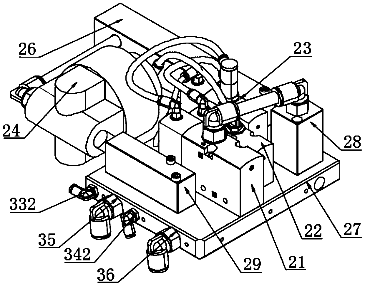
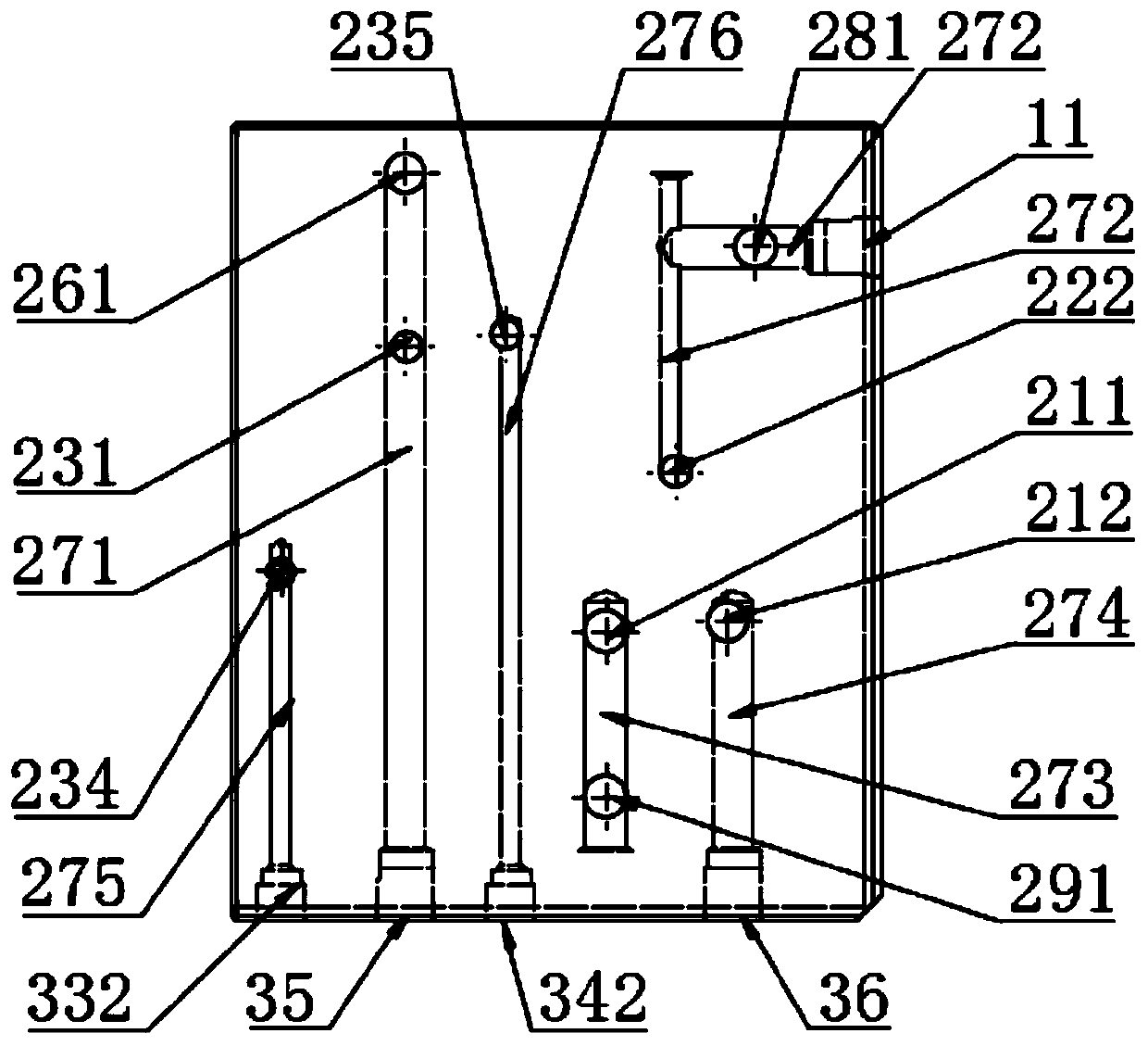
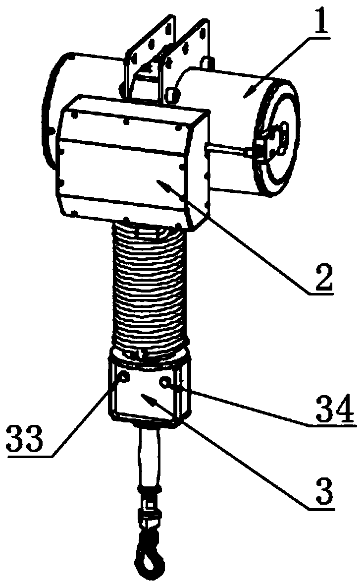
[0022] Such as Figure 1-Figure 4 As shown, an air-controlled self-induction pneumatic balance crane includes an air suspension main body 1 and an operating device 3 connected through an air control box 2, and the operating device 3 is provided with a lifting switch 31, a lowering switch 32, a button A 33 and a button B 34. The air control box 2 is provided with a fixedly connected air circuit board 27, and the air circuit board 27 is provided with fixedly connected valve C 21, valve B 22, valve A 23, air intake connector 26, connector A 28 and Connecting piece B 29, an air-controlled decompression valve 24 is provided between the intake connecting piece 26 and connecting piece B 29, connecting piece B 29 communicat...


PUM


Abstract

The invention relates to a pneumatic control self-induction pneumatic balance crane, and belongs to the technical field of pneumatic control self-induction pneumatic balance cranes. The pneumatic control self-induction pneumatic balance crane comprises a pneumatic crane main body and an operating device which are connected through a pneumatic control box; the operating device is provided with a lifting switch, a descending switch, a first button and a second button; a gas circuit board is fixedly connected in the pneumatic control box; a third valve, a second valve, a first valve, a gas inletconnecting part, a first connecting part and a second connecting part which are fixedly connected are arranged on the gas circuit board; and a gas control pressure reducing valve is arranged between the gas inlet connecting part and the second connecting part, the second connecting part is in communication with the third valve through the gas circuit board, and the third valve and the second valveare connected with the pneumatic hoist body in parallel. The equipment is simple in structure and easy to operate, through the combination of the first valve, the third valve, the second valve, the lifting switch, the descending switch, the first button and the second button, the hoisting precision of hoisting and moving objects of different weights is effectively improved, the hoisting range ofthe pneumatic balance device is enlarged, the objects are conveniently hoisted and moved, the working cycle time is shortened, and the operation safety is improved.

Description

technical field [0001] The invention relates to an air-controlled self-induction pneumatic balancing crane, which belongs to the technical field of pneumatic balancing crane control devices. Background technique [0002] At present, the light and small hoisting equipment used in China is mainly electric hoist, pneumatic hoist, etc., and the hoisting accuracy of such equipment cannot be guaranteed. Pneumatic balancer can realize fast moving and precise assembly of objects. The existing pneumatic balancer control system solves some technical problems, but there are still two technical problems: one is the pneumatic balance system that can realize the suspension of objects, but It can only realize the precise lifting and moving of objects of constant weight, but cannot realize the lifting and moving of objects of different weights, thus limiting the lifting range of the pneumatic balancer; the other is the electric servo balance system that can realize the lifting of objects of...

Claims


Application Information

Patent Timeline
Patent Type & Authority Applications(China)
IPC IPC(8): B66F3/42
CPCB66F3/242B66F3/247B66F3/42
Inventor 于冬文金立业
Owner 烟台红鸟智能科技有限公司
Why Eureka
Try Eureka