Al technical title is built by PatSnap Al team. It summarizes the technical point description of the patent document.
A dust removal device and multi-functional technology, applied in road cleaning, construction, cleaning methods, etc., can solve the problems of inconvenient ground humidification, inconvenient adjustment of the height of the sweeping device, inconvenient to support power equipment, etc., and achieve the effect of convenient adjustment.
Inactive Publication Date: 2020-08-21
滨州市无棣县可歆进出口贸易有限公司
View PDF8 Cites 1 Cited by
Summary
Abstract
Description
Claims
Application Information
AI Technical Summary
This helps you quickly interpret patents by identifying the three key elements:
Problems solved by technology
Method used
Benefits of technology
Problems solved by technology
[0005] In order to solve the above-mentioned technical problems, the present invention provides a multi-functional factory ground dust removal equipment to solve the existing problems in the existing dust removal equipment that it is inconvenient to adjust the height of the sweeping device during the working process, it is inconvenient to support the power equipment and it is inconvenient to carry out absorption and sweeping. The problem of dust and inconvenient humidification of the ground
Method used
Image
Click on the blue label to locate the original text in one second.
Reading with bidirectional positioning of images and text.
Examples
Embodiment Construction
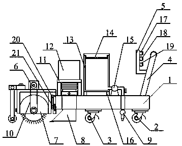
[0037] The present invention is described in detail below in conjunction with accompanying drawing, as appendedfigure 1 And attached figure 2 As shown, the multifunctional factory floor dust removal equipment includes a mobile seat 1, a universal wheel 2, a directional wheel 3, a push rod 4, an L-shaped control panel 5, a supporting power seat structure 6, and an adjustable cleaning cover structure 7. Telescopic collection pipe structure 8, adjustable humidification pipe structure 9, V-belt 10, first inverted U-shaped fixing seat 11, vacuum cleaner 12, bucket 13, T-shaped filter pipe 14, spray pump 15, support block 16, cleaning switch 17 , dust suction switch 18, spray switch 19, sliding hole 20 and wing bolt 21, described universal wheel 2 is respectively bolted on the lower end right side of mobile seat 1; described directional wheel 3 is respectively bolted on mobile seat 1 at the middle position on the left side of the lower end; the lower end bolt of the push rod 4 is c...
PUM
Abstract
The invention provides multifunctional factory ground dust removal equipment, which comprises a movable seat, universal wheels, directional wheels, a push rod, an L-shaped control panel, a supportablepower seat structure, an adjustable sweeping cover structure, a telescopic collecting pipe structure, an adjustable humidifying pipe structure, a V belt, a first inverted-U-shaped fixing seat, a dustcollector, a water bucket, a T-shaped filtering pipe, a spraying pump, a supporting block, a sweeping switch, a dust collection switch, a spraying switch, a sliding hole and a swing-shaped bolt, wherein the universal wheels are in bolted connection with the right side of the lower end of the movable seat respectively; and the directional wheel is in bolted connection with the middle position of the left side of the lower end of the movable seat. Through the arrangement of the movable seat, the sliding hole, the wing-shaped bolt and the second inverted-U-shaped fixing seat, the wing-shaped bolt can be loosened in the working process to pull the sweeping cover up and down, the height of a sweeping roller and the height of sweeping bristles can be conveniently adjusted for dust removal work,and adjustment work in the dust removal process is facilitated.
Description
technical field [0001] The invention belongs to the technical field of dust removal equipment, in particular to multifunctional factory ground dust removal equipment. Background technique [0002] The factory is easy to generate dust during the production process. The dust generated will not only fall on the surface of the equipment, but also on the ground, which is easy to pollute the environment on the factory floor. [0003] However, the existing dust removal equipment still has the problems of inconvenient adjustment of the height of the sweeping device during work, inconvenient support of power equipment, inconvenient absorption of dust picked up and inconvenient humidification of the ground. [0004] Therefore, it is very necessary to invent multifunctional factory ground dust removal equipment. Contents of the invention [0005] In order to solve the above-mentioned technical problems, the present invention provides a multi-functional factory ground dust removal eq...
Claims
Application Information
Patent Timeline
Application Date:The date an application was filed.
Publication Date:The date a patent or application was officially published.
First Publication Date:The earliest publication date of a patent with the same application number.
Issue Date:Publication date of the patent grant document.
PCT Entry Date:The Entry date of PCT National Phase.
Estimated Expiry Date:The statutory expiry date of a patent right according to the Patent Law, and it is the longest term of protection that the patent right can achieve without the termination of the patent right due to other reasons(Term extension factor has been taken into account ).
Invalid Date:Actual expiry date is based on effective date or publication date of legal transaction data of invalid patent.