Constant tension conveying mechanism of material unit

A technology of conveying mechanism and constant tension, which is applied in the direction of winding strips, thin material processing, transportation and packaging, etc., which can solve the problems of unsmooth conveying and unavailable supply, and achieve simple structure, guarantee of conveying accuracy and convenient use Effect

Inactive Publication Date: 2020-08-25
中山达远智造有限公司
View PDF7 Cites 2 Cited by
  • Summary
  • Abstract
  • Description
  • Claims
  • Application Information

AI Technical Summary

Problems solved by technology

[0003] However, in the process of conveying, the tension of the material will change, resulting in the inability to carry out the conveying smoothly, and it is necessary to manually adjust the tension, and it is impossible to provide a system that can automatically detect the tension to adjust the conveying speed and tension. Conveyor

Method used


Image

  • Constant tension conveying mechanism of material unit
  • Constant tension conveying mechanism of material unit
  • Constant tension conveying mechanism of material unit

Examples


Embodiment Construction

[0031] The following will clearly and completely describe the technical solutions in the embodiments of the present invention with reference to the accompanying drawings in the embodiments of the present invention. Obviously, the described embodiments are only some, not all, embodiments of the present invention. Based on the embodiments of the present invention, all other embodiments obtained by persons of ordinary skill in the art without making creative efforts belong to the protection scope of the present invention.

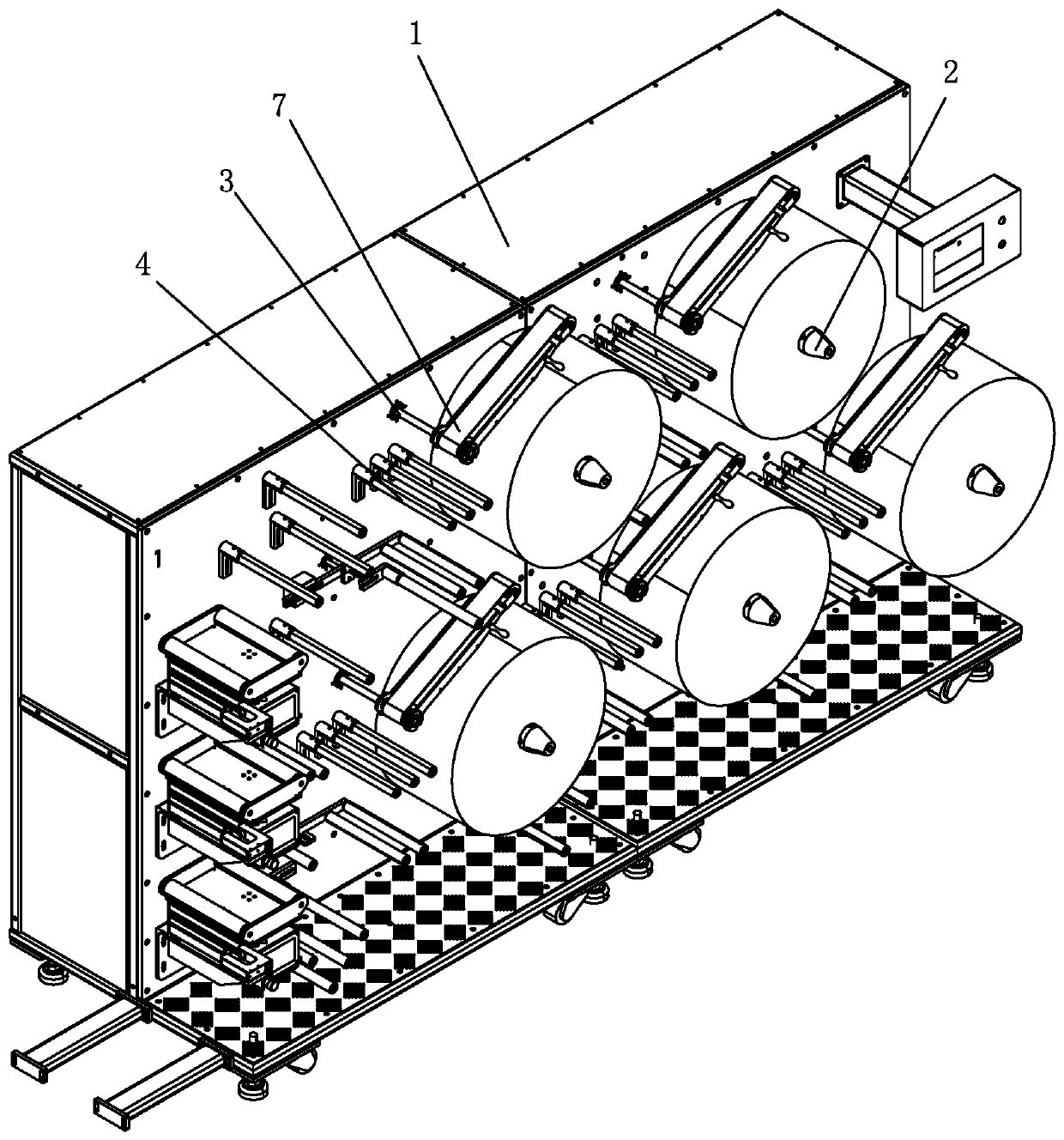
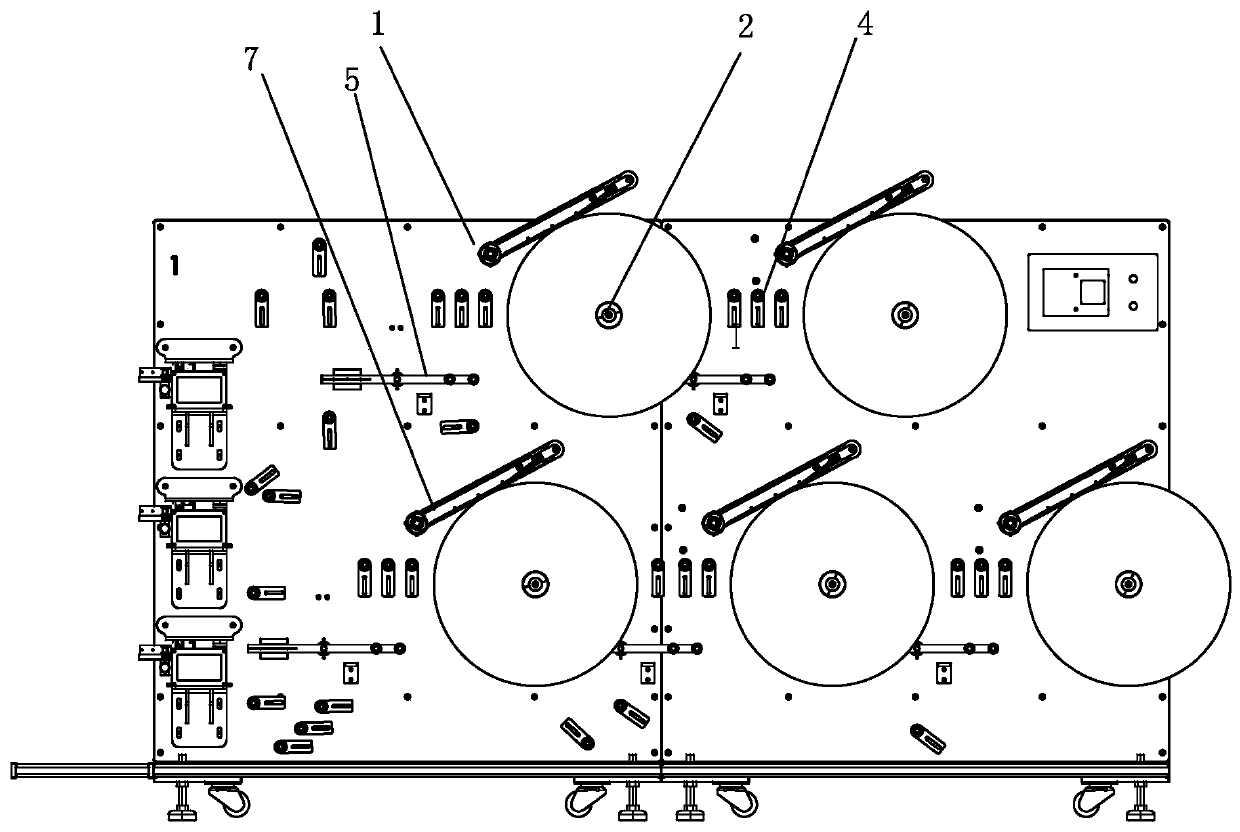
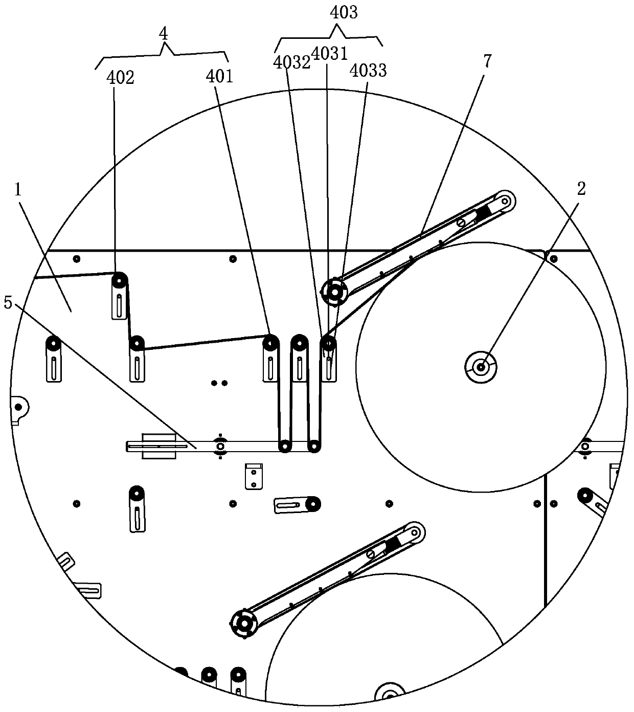
[0032] see Figure 1-7 , the present invention provides a technical solution:

[0033] A material unit constant tension conveying mechanism, including a device body 1, on which a coil material rotating shaft 2 for installing a coil material is arranged,

[0034] The freely swinging transmission belt 7 is arranged on one side of the coil material rotating shaft 2 and is closely attached to the surface of the material to drive the material out;

[0035] A belt...


PUM


Abstract

The invention discloses a constant tension conveying mechanism of a material unit. The mechanism comprises an equipment body, a free swing transmission belt, a belt rotating speed controller, a material conveying roller unit and a tension detection controller, wherein a roll material rotating shaft for mounting a roll material is arranged on the equipment body; the free swing transmission belt isarranged on one side of the roll material rotating shaft and clings to the surface of the material to deliver and drive the material; the belt rotating speed controller is connected to the free swingtransmission belt and is used for controlling the belt rotating speed of the free swing transmission belt; the material conveying roller unit is arranged on one side of the roll material rotating shaft and is connected to the material to assist in material output; and the tension detection controller is arranged on one side of the material conveying roller unit and is connected to and conveys thematerial and detects the tension of the material. The constant tension conveying mechanism can adjust the tension automatically to guarantee smooth conveyance without adjusting the tension manually, so that the conveying precision and the conveying quality of the material are guaranteed. The constant tension conveying mechanism is simple in structure and convenient to use.

Description

technical field [0001] The present invention relates to material delivery mechanisms. Background technique [0002] Material conveying device, a set of equipment for conveying coiled materials, can replace manual conveying, effectively increase work efficiency, reduce the error rate of manual mistakes and save manpower and material resources. [0003] However, in the process of conveying, the tension of the material will change, resulting in the inability to carry out the conveying smoothly, and the tension needs to be adjusted manually, and it is impossible to provide a system that can automatically detect the tension to adjust the conveying speed and tension. delivery mechanism. [0004] Therefore, the existing material conveying mechanism is further improved. Contents of the invention [0005] The object of the present invention is to provide a material unit constant tension conveying mechanism. [0006] In order to achieve the above object, the present invention ado...

Claims


Application Information

Patent Timeline
Patent Type & Authority Applications(China)
IPC IPC(8): B65H23/182B65H16/00B65H20/02B65H26/04
CPCB65H16/00B65H20/02B65H23/1825B65H26/04B65H2515/31
Inventor 刘庆伦李庆达晏华成钟嘉明魏日鑫韦世贵邹炜演刘细霞张亚民唐林新曹传永丁立刚田永明曹传舟陈生荣
Owner 中山达远智造有限公司
Why Eureka
Try Eureka