
Navigation radar antenna multi-angle rotating support

A technology of rotating bracket and navigation radar, which is applied in the field of navigation, can solve the problems of poor stability, rapidity and anti-interference ability, and difficulty in realizing fixed-point steering of radar antenna, so as to achieve rapid stabilization of antenna height, adjustment of antenna height, and stable steering Effect

Active Publication Date: 2020-08-25
合肥君百防务科技有限公司
View PDF9 Cites 1 Cited by
  • Summary
  • Abstract
  • Description
  • Claims
  • Application Information

AI Technical Summary

Problems solved by technology

[0005] Aiming at the deficiencies in the prior art, the present invention provides a navigation radar antenna multi-angle rotating bracket, which has the advantages of more stable, faster and more convenient steering of the radar antenna, and solves the problem that the traditional radar antenna steering control is mainly through the gear plane structure. Realization, this kind of gear structure plane is difficult to realize the fixed-point steering of the radar antenna, and its stability, rapidity and anti-interference ability are poor

Method used


Image

  • Navigation radar antenna multi-angle rotating support
  • Navigation radar antenna multi-angle rotating support
  • Navigation radar antenna multi-angle rotating support

Examples


Embodiment Construction

[0023] The following will clearly and completely describe the technical solutions in the embodiments of the present invention with reference to the accompanying drawings in the embodiments of the present invention. Obviously, the described embodiments are only some, not all, embodiments of the present invention. Based on the embodiments of the present invention, all other embodiments obtained by persons of ordinary skill in the art without making creative efforts belong to the protection scope of the present invention.

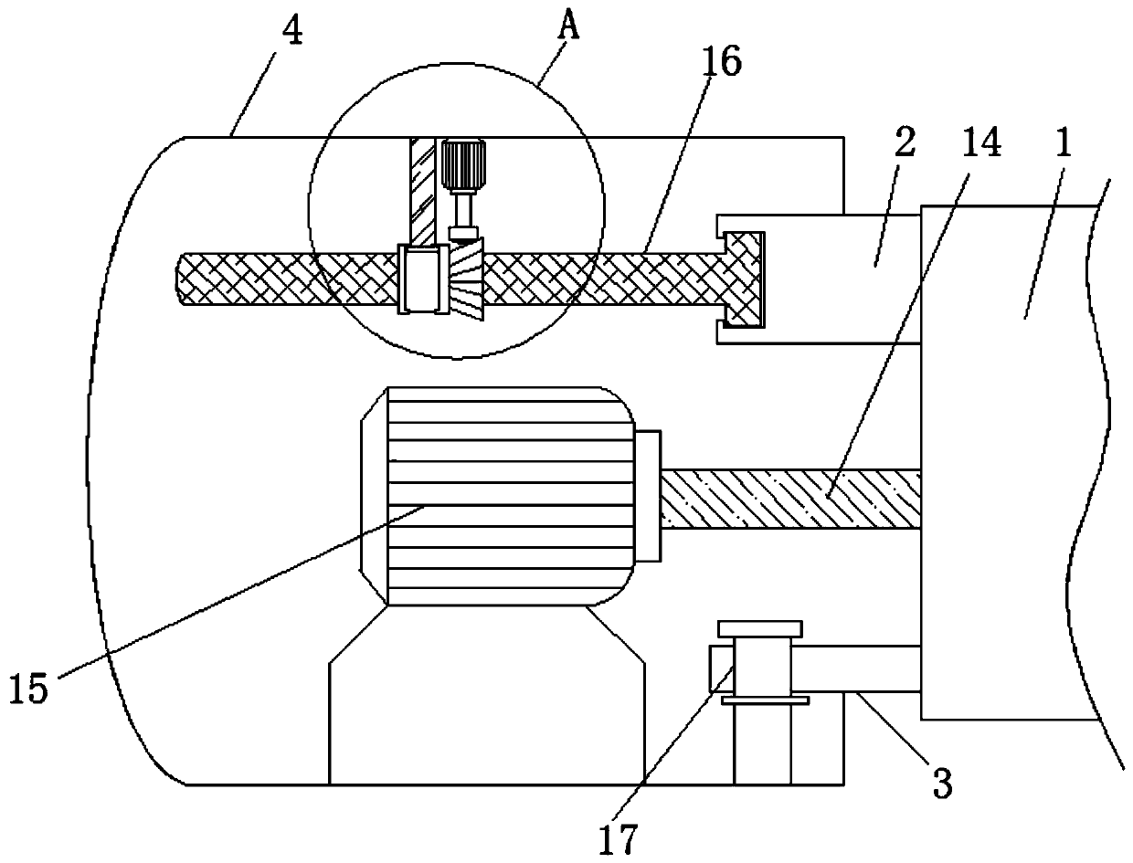
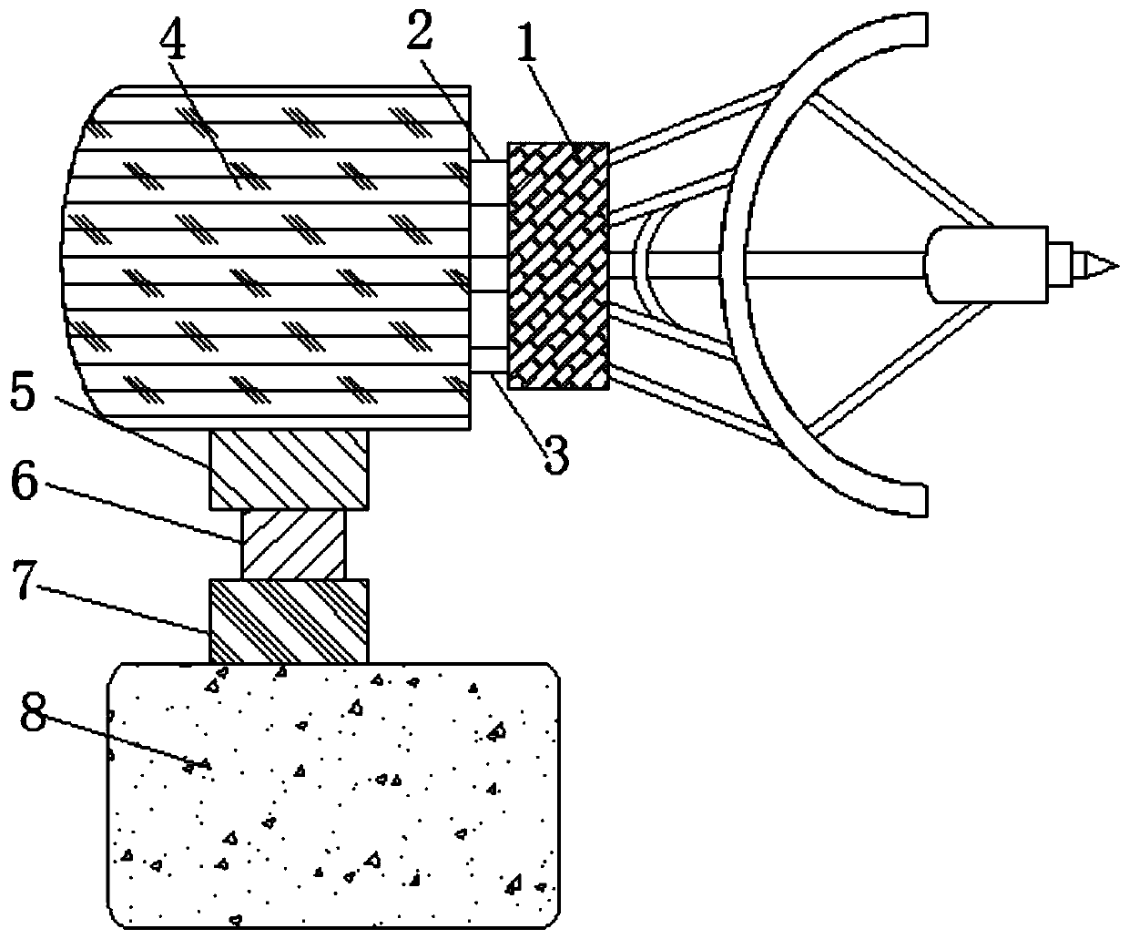
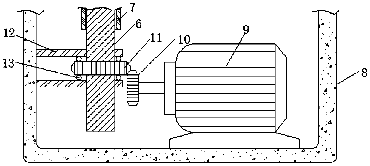
[0024] see Figure 1-5 , a navigation radar antenna multi-angle rotating bracket, comprising an antenna 1, the left side of the antenna 1 is fixedly connected with a tilting bracket 2, the left side of the antenna 1 is fixedly connected with a fixed bracket 3, and the fixed bracket 3 is below the tilting bracket 2, tilted The side of the support 2 away from the antenna 1 is movably connected with a steering mechanism 4, the bottom of the steering mechanism 4 i...


PUM


Abstract

The invention relates to the technical field of navigation, and discloses a navigation radar antenna multi-angle rotating support comprising an antenna. The left side of the antenna is fixedly connected with an inclined support, and the left side of the antenna is fixedly connected with a fixed support. According to the multi-angle rotating support for the navigation radar antenna, a first motor is started to enable a first gear to drive a second gear to rotate, and the second gear is in threaded connection with a telescopic rod, so that the telescopic rod can move up and down to further enable the antenna to move up and down, and the effect of quickly and stably adjusting the height of the antenna is achieved; a third motor is started to enable a fourth gear to drive a third gear to rotate, at the moment, the third gear can drive a threaded rod to rotate, and the threaded rod moves left and right; the inclination angle of the antenna is further changed; a second motor is started to enable the antenna to rapidly and stably rotate, and therefore the effect that the radar antenna is more stable, faster and more convenient to steer is achieved.

Description

technical field [0001] The invention relates to the technical field of navigation, in particular to a navigation radar antenna multi-angle rotating bracket. Background technique [0002] Navigation is a research field that focuses on monitoring and controlling the process of moving a craft or vehicle from one place to another. Navigation mainly includes: land navigation, ocean navigation, aviation navigation and space navigation. Navigation can refer to the process of determining position and direction. Any skill or research. All navigation involves any skill or study of determining position and direction. [0003] In marine navigation, radar is often used to detect position and navigation direction. Radar mainly detects direction by radiating and receiving electromagnetic waves. When radar is performing direction detection, it is necessary to adjust the steering of the antenna to expand the detection range. The traditional radar antenna steering The control is mainly real...

Claims


Application Information

Patent Timeline
IPC IPC(8): H01Q1/12H01Q3/08
CPCH01Q1/12H01Q3/08
Inventor 潘永平
Owner 合肥君百防务科技有限公司
Learn More