[0020] The technical solutions of the present invention will be further described below in conjunction with the accompanying drawings and through specific implementation methods.
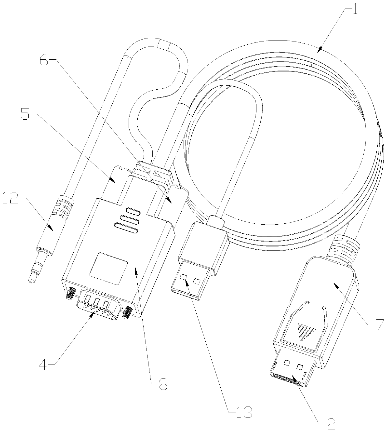
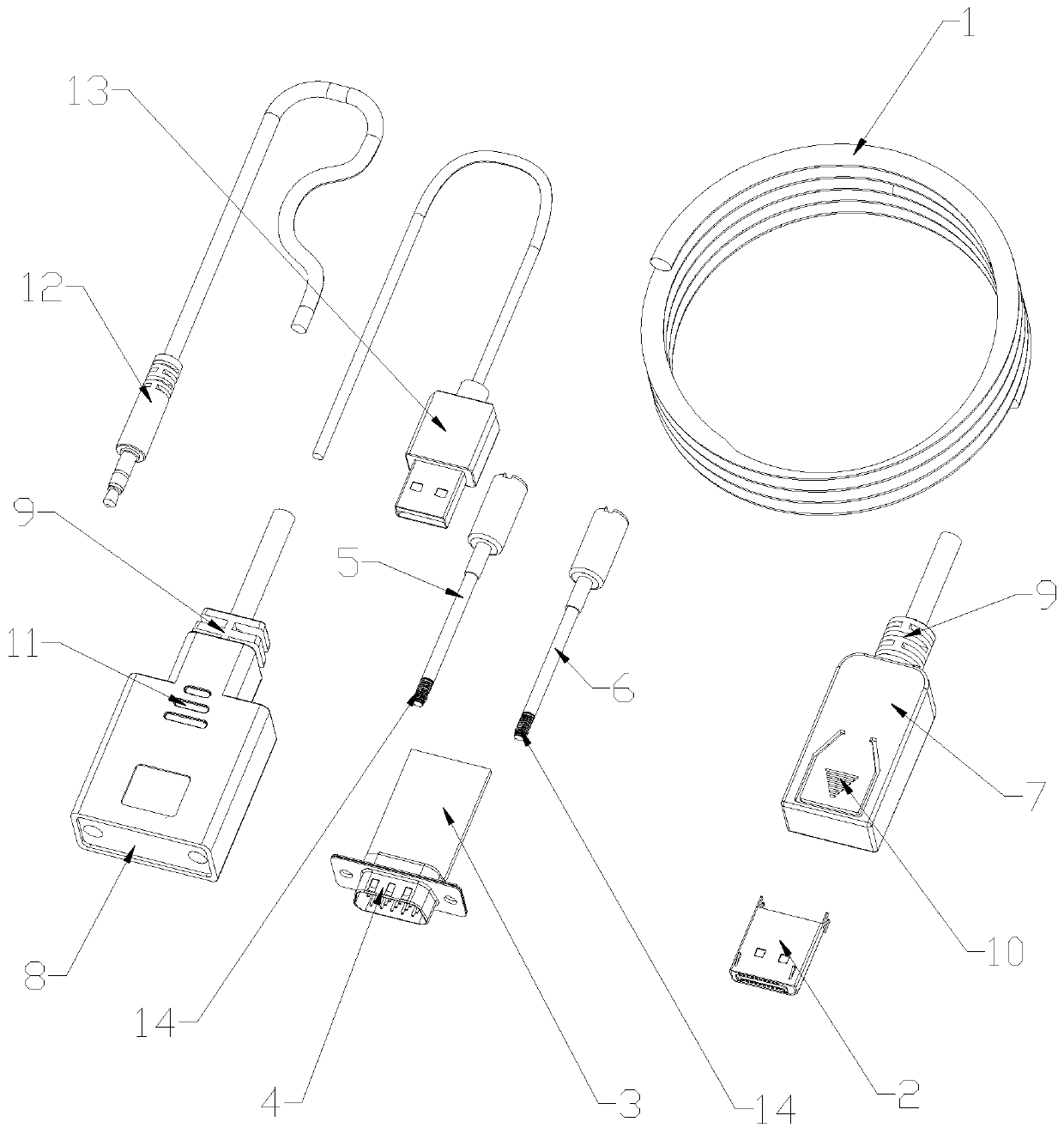
[0021] like Figure 1 to Figure 2 As shown, in this embodiment, an analog signal is transferred to a digital signal conversion cable, including a connecting line 1, a DP ultrasonic upper cover, a DP ultrasonic lower cover, a DP plug 2, a VGA ultrasonic upper cover, a VGA ultrasonic The lower cover, the circuit board 3, the VGA connector 4, the first fixing screw 5 and the second fixing screw 6, the edge of the DP ultrasonic upper cover is clamped with the edge of the DP ultrasonic lower cover to form a DP cover 7, the DP The connector is located at the front end of the DP cover 7, and the edge of the VGA ultrasonic upper cover is engaged with the edge of the VGA ultrasonic lower cover to form a VGA cover 8. The VGA connector 4 is located at the front end of the VGA cover 8. The circuit board 3 is inside the VGA ultrasonic upper cover and the VGA ultrasonic lower cover, the signal connection between the VGA connector 4 and the circuit board 3, and one end of the connection line 1 is connected to the DP cover 7 The other end of the connecting wire 1 is connected to the VGA cover 8, the first fixing screw 5 and the second fixing screw 6 are respectively located on both sides of the VGA cover 8, the first fixing screw Both the screw 5 and the second fixing screw 6 pass through the VGA cover 8 and the VGA connector 4 .
[0022] VGA (Video Graphics Array), usually refers to the VGA interface. The VGA interface is an interface for outputting analog signals on the graphics card. The VGA interface is a D-type interface with a total of 15 pins, divided into three rows, five in each row.
[0023] DP (DisplayPort) is a digital video interface standard developed by an alliance of PC and chip manufacturers and standardized by the Video Electronics Standards Association (VESA). This interface is free of certification and license fees, and is mainly used for connecting video sources and devices such as monitors, and also supports carrying audio, USB and other forms of data.
[0024] The DP connector is connected to the display device, the VGA connector 4 is connected to the output device, the circuit chip installed on the circuit board 3 is bridged, and the analog signal is converted into a digital signal, and then converted from a digital signal to a digital signal. The digital signal is output, and the signal transfer function is completed after three signal conversions (VGA to HDMI, HDMI to DP). It is characterized by multiple conversions to achieve mutual connection and communication of the interface, and can convert audio and video signals synchronously.
[0025] Specifically, the end of the connection line 1 close to the DP plug 2 and the end of the connection line 1 close to the VGA plug are both provided with a molded SR9.
[0026] SR means that a positioning buckle is formed on the line, and it is formed after welding between the lines, that is, a line needs to be formed into a fixed thing. SR is the abbreviation of STRAIN RELIEF, and the Chinese translation means overflow.
[0027] The outer side of the DP cover 7 is provided with triangular anti-skid lines 10 .
[0028] The triangular anti-skid lines 10 can increase the frictional force of the human hand holding the DP.
[0029] The outer side of the VGA cover 8 is provided with cooling holes 11 .
[0030] The heat generated when working on the circuit board 3 will be dissipated outwards through the heat dissipation holes 11 .
[0031] An audio input connector 12 and a USB power supply interface 13 are also connected to the VGA cover 8 .
[0032] The audio input connector 12 and the USB power supply interface 13 can increase additional functions of the product, which is more in line with modern requirements.
[0033] One end of the first fixing screw 5 and the second fixing screw 6 close to the connecting wire 1 is provided with a slotted hole.
[0034] Manually rotate the slotted holes on the first fixing screw 5 and the second fixing screw 6 with a flat screwdriver, so that the VGA connector 4 can be connected to the output device and relatively fixed.
[0035] Specifically, the ends of the first fixing screw 5 and the second fixing screw 6 away from the connecting wire 1 are both provided with threads 14 connected to the outside.
[0036] In this embodiment, the connection cable 1 is a DP cable.
[0037] image 3 VGA interface: used to connect to the external VGA interface; Figure 4 It is an explicit conversion module: VGA is converted to HDMI display output; Figure 5 For the filter circuit: V33, AV33, AV33_AU three-way filter circuit, to provide a stable voltage for the IC; Image 6 For the filter circuit: V18, AV18_TX, AV18 three-way filter circuit, to provide a stable voltage for the IC; Figure 7 For the power module: provide 3.3V voltage for the VGA to HDMI module IC; Figure 8 For the power module: provide 1.8V voltage for the VGA to HDMI module IC; Figure 9 HDMI to DP module: convert HDMI signal to DP signal output; Figure 10 For the LD0 circuit: convert 5V to 3.3V output, and provide 3.3V voltage to the HDMI to DP IC; Figure 11 For DCDC circuit: convert 5V voltage into 1.2V voltage, and provide 1.2V voltage for HDMI to DP IC; Figure 12 For DCDC circuit: convert 5V voltage into 1.8V voltage, and provide 1.8V voltage for HDMI to DP IC; Figure 13 logic circuits for the entire product.
[0038] It should be stated that the above-mentioned specific implementation methods are only preferred embodiments of the present invention and the applied technical principles. Within the technical scope disclosed in the present invention, any changes or substitutions that are easily conceivable by those skilled in the art, All should be covered within the protection scope of the present invention.