
Insert molding mold with insert local heating function and machining method thereof

A local heating and insert molding technology, which is applied to household components, household appliances, and other household appliances, can solve the problems of melting and discoloration of the plating layer of metal terminals, and achieve the effect of ensuring injection molding quality and production yield

Pending Publication Date: 2020-08-28
SUZHOU HUAZHAN SPACE APPLIANCE
View PDF0 Cites 0 Cited by
  • Summary
  • Abstract
  • Description
  • Claims
  • Application Information

AI Technical Summary

Problems solved by technology

[0004] The invention overcomes the deficiencies of the prior art and provides an insert molding mold in which the insert is partially heated, which can improve the problem that the metal terminal plating layer of the connector is prone to melting and discoloration during injection molding of the mold

Method used


Image

  • Insert molding mold with insert local heating function and machining method thereof
  • Insert molding mold with insert local heating function and machining method thereof
  • Insert molding mold with insert local heating function and machining method thereof

Examples


Embodiment 1

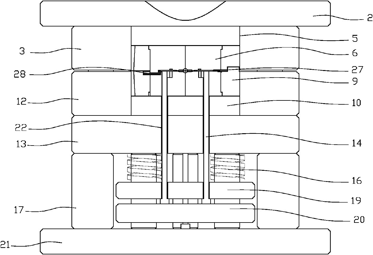
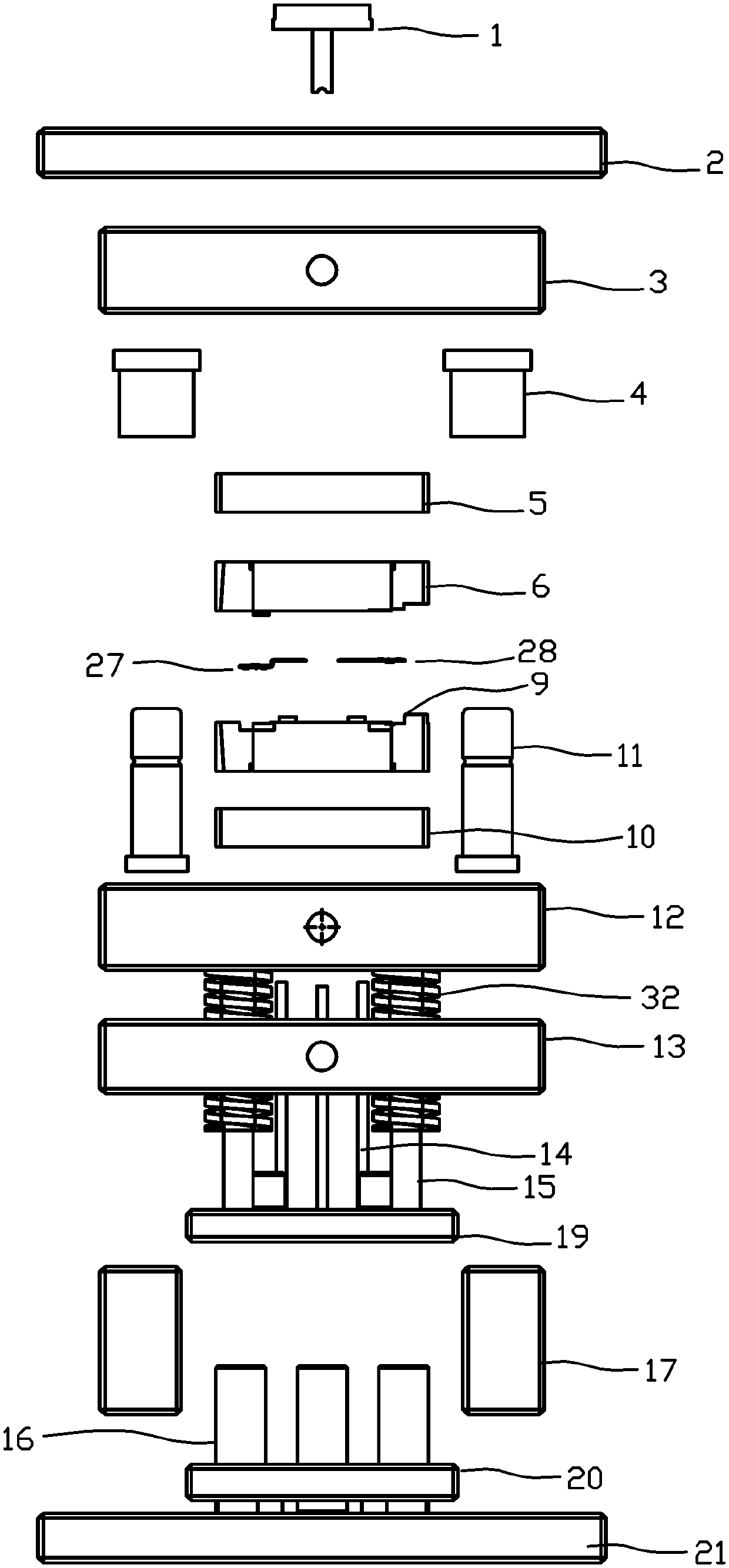
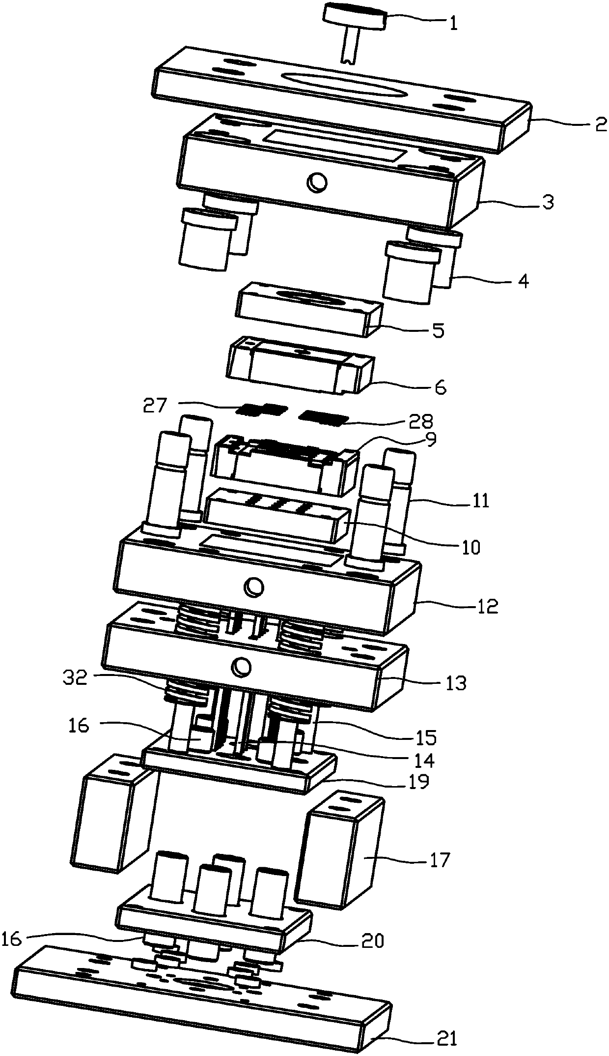
[0046] Such as Figure 13~Figure 16 As shown, the two groups of workpieces processed by the present invention include a group of workpiece one 27 and a group of workpiece two 28 . Work piece one 27 includes metal terminal one 271 . One end of the metal terminal one 271 is injection-molded with the insulator 26 through the molding die of the present application. Work piece two 28 includes metal terminal two 281 . One end of the second metal terminal 281 is injection-molded with the insulator 26 through the molding die of the present application. The first metal terminal 271 and the second metal terminal 281 are both sheet structures. The difference between the second workpiece 28 and the first workpiece 27 is that the first metal terminal 271 is provided with a bent portion, and the second metal terminal 281 is a planar structure.

[0047] Such as Figure 1~Figure 12 As shown in the figure, an insert molding mold with partially heated inserts includes a fixed mold and a mov...

Embodiment 2

[0054] The processing method of the insert molding mold in which the insert is locally heated in Embodiment 1 comprises the following steps,

[0055] Step 1, loading; put the workpiece into the storage cavity of workpiece 1 27 and workpiece 2 28, store workpiece 1 27 and workpiece 2 28 through the movable mold core 9, and the ends of workpiece 1 27 and workpiece 2 28 that need to be injected correspond to each other Place in the injection molding cavity 36 in the receiving cavity of workpiece one 27 and workpiece two 28;

[0056] Step 2, position limiting, mold closing; press down the mold so that the fixed mold and the movable mold are pressed together up and down, and the workpiece one 27 and the workpiece two 28 are limited in the workpiece receiving cavity between the fixed mold and the movable mold;

[0057] Step 3, processing injection molding; injecting workpiece 1 27 and workpiece 2 28 in the injection cavity 36 through sprue bushing 1; injecting through horizontal exh...


PUM


Abstract

The invention discloses an insert molding mold with an insert local heating function. The insert molding mold comprises a fixed mold and a movable mold capable of being opened and closed in a reciprocating mode relative to the fixed mold, at least one workpiece storage cavity used for storing a workpiece is formed between the fixed mold or / and the movable mold, exhaust grooves are formed in the fixed mold or / and the movable mold, each workpiece storage cavity comprises a positioning cavity and an injection molding cavity, and a sprue bush extending to the injection molding cavities is furtherarranged on the fixed mold. The provided insert molding mold with the insert local heating function can solve the problem that an electroplated layer of a metal terminal of a connector is prone to melting and discoloring during injection molding of the mold.

Description

technical field [0001] The invention relates to the technical field of in-mold injection molding, in particular to an insert molding mold in which the insert is locally heated and a processing method thereof. Background technique [0002] Among the existing connectors, the production method of the general terminal is the insert molding technology (Insert Molding). This method is to put the metal terminal into the designed preset position in the mold before the insulator body is formed, and then perform the injection molding Molding, injection of thermoplastic or thermoset material, allowing the molten material to solidify in conjunction with the insert to form a complete terminal. The advantages of this technology are: enhancing the connection strength between the metal terminal and the insulating body, avoiding deformation of the metal terminal, and improving quality and yield. In addition to being applied to connector products, this technology can also be applied to other...

Claims


Application Information

Patent Timeline
IPC IPC(8): B29C45/34B29C45/14B29L31/36
CPCB29C45/0025B29C45/14639B29C45/34B29L2031/36
Inventor 孙淇王永东丁涛
Owner SUZHOU HUAZHAN SPACE APPLIANCE
Learn More