
a pair of sf 6 An intelligent calibrator for comprehensive evaluation of the life cycle of density relays

A technology of density relay and life cycle, which is applied in the field of calibrator, can solve the problem of inconvenient adjustment of detection position and angle, and achieve the effect of improving convenience, high stability, and easy activity adjustment

Active Publication Date: 2022-01-04
FUZHOU BRANCH XIAMEN JIAHUA ELECTRIC POWER TECH
View PDF5 Cites 0 Cited by
  • Summary
  • Abstract
  • Description
  • Claims
  • Application Information

AI Technical Summary

Problems solved by technology

[0004] The detection method and device structure of the existing detection device are relatively mature, but it is inconvenient to adjust the detection position and angle during use

Method used


Image

  • a pair of sf  <sub>6</sub> An intelligent calibrator for comprehensive evaluation of the life cycle of density relays
  • a pair of sf  <sub>6</sub> An intelligent calibrator for comprehensive evaluation of the life cycle of density relays
  • a pair of sf  <sub>6</sub> An intelligent calibrator for comprehensive evaluation of the life cycle of density relays

Examples


Embodiment 1

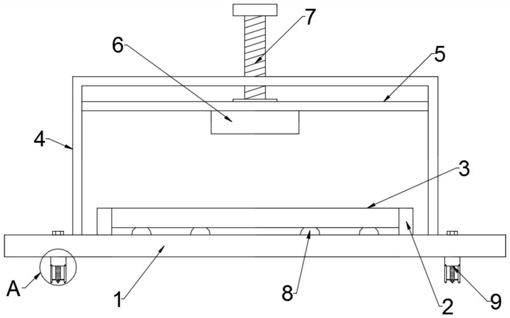
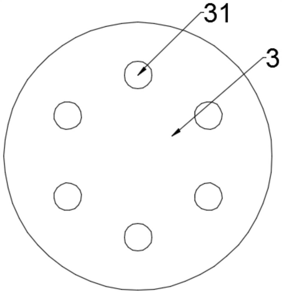
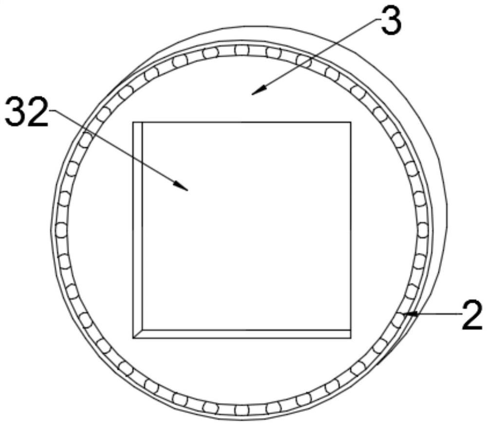
[0023] see Figure 1~3 , in the embodiment of the present invention, a kind of SF 6 An intelligent calibrator for comprehensive evaluation of the life cycle of a density relay, including a base plate 1 and a calibrator body 6, the upper end of the base plate 1 is symmetrically connected to both sides, and a support 4 is arranged on the upper end of the base plate 1, and a lifting plate 5 is provided on the support 4 for sliding fit. The calibrator body 6 is installed on the side of the lifting plate 5 close to the bottom plate 1, and the upper end of the bracket 4 is threaded and movable to be provided with a first adjusting rod 7, and the end of the first adjusting rod 7 and the The lifting plate 5 is rotatably connected by bearings, the relative position of the upper end of the base plate 1 and the calibrator body 6 is provided with a placement structure for arranging and detecting products through limit rotation, and the lifting adjustment is arranged symmetrically on both ...

Embodiment 2

[0027] see Figure 4 , in the embodiment of the present invention, a kind of SF 6 An intelligent calibrator for comprehensive evaluation of the life cycle of density relays. On the basis of Embodiment 1, the support member 9 includes a pad 91, a support rod 93 and a suction cup 96, and the pad 91 is fixed on the lower end of the bottom plate 1. A plurality of sets of support rods 93 are evenly distributed on the lower edge of the pad 91, and the support rods 93 and the pad 91 are rotatably connected, and the ends of the support rods 93 away from the pad 91 are hemispherical. The opposite side of the support rod 93 is embedded with a chute, the middle part of the pad 91 is provided with a second adjustment rod 92, and the end of the second adjustment rod 92 is rotatably connected with a sliding plate 94 through a bearing. The sliding plate 94 A slide bar 95 is embedded in the position opposite to the chute on the edge and the support bar 93, and one end of the slide bar 95 is ...


PUM


Abstract

The present invention disclosed a kind of pair SF 6 The intelligent verification instrument comprehensive judgment of the life cycle of density relay, including the bottom plate and the inspection device body, which is provided with a bracket on both sides of the upper end of the bottom plate.The installation settings are located on the side of the bottom plate near the bottom plate, and the upper end of the bracket has the first adjustment rod through the threaded activity through the activity of the activity.The upper end has a resettlement structure through a limit rotation. The symmetrical settings on both sides of the bottom plate are set with supporting parts with lifting adjustment.The position of the laboratory of the middle school of the present invention is easy to adjust the activity, and the resettlement structure used for resetting the product can be transferred to the limit settings, so that the convenience of the detection can be improved;, And can obtain higher stability and improve the effect of use.

Description

technical field [0001] The invention relates to the technical field of calibrator, in particular to a 6 An intelligent calibrator for comprehensive evaluation of the life cycle of density relays. Background technique [0002] Substation plays the role of "energy transmission artery" in economic and social development, and its importance is self-evident. As a colorless, odorless, non-toxic and non-combustible gas arc extinguishing medium, SF6 has been widely used in electrical equipment, replacing traditional oil medium arc extinguishing electrical equipment, and has been widely used in power grids. [0003] But SF 6 SF often occurs in electrical equipment during daily operation 6 Gas leakage defects, the leakage point mainly appears on the flange surface or SF 6 density relay. The commonly used leak detection method today is to use SF after a certain period of time after sealing the leak point. 6 Probe into the halogen gas detector or directly use the foam detection me...

Claims


Application Information

Patent Timeline
Patent Type & Authority Patents(China)
IPC IPC(8): G01M3/20G01M3/04
CPCG01M3/20G01M3/207G01M3/04
Inventor 游骏标林芬
Owner FUZHOU BRANCH XIAMEN JIAHUA ELECTRIC POWER TECH
Learn More