Balloon dilatation catheter tester
A technology for dilating catheters and testing instruments, applied in the medical field, can solve the problems of inconvenient detection of catheters and balloons, inconvenient opening, placement and disassembly, and inconvenient device sealing adjustment operations, etc. Stability effect, easy detection effect
- Summary
- Abstract
- Description
- Claims
- Application Information
AI Technical Summary
Problems solved by technology
Method used
Image
Examples
Embodiment 1
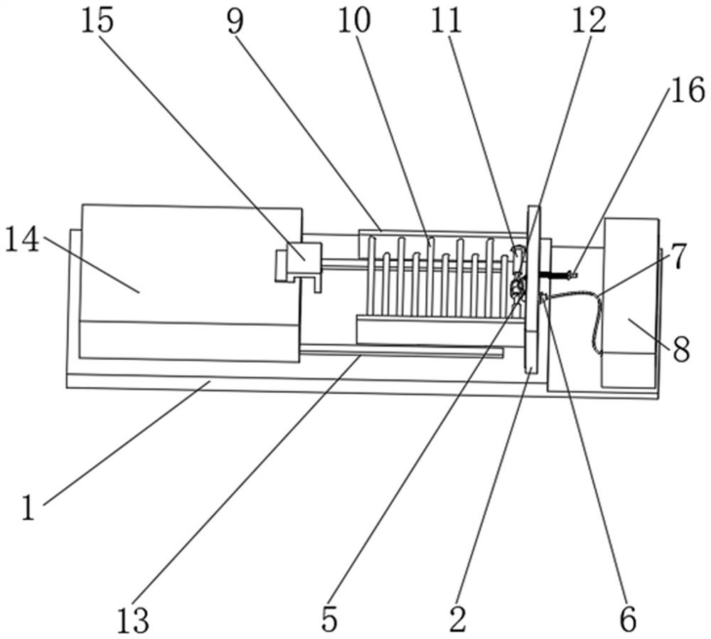
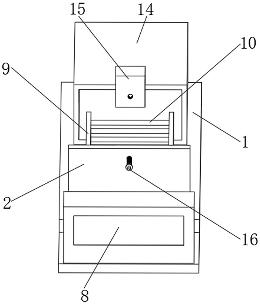
[0029] see figure 1 , image 3 , Figure 5 and Image 6 As shown, a balloon dilatation catheter tester includes a base plate 1, a side plate 9 and a sliding groove 13, the top of the base plate 1 is provided with a vertical plate 2, and the outer wall of the vertical plate 2 is provided with a slot 3, and the slot 3 The side of the vertical plate 2 is provided with a sealing strip 4, the middle position of the vertical plate 2 is provided with a clamping mechanism 5, and the bottom of the clamping mechanism 5 is provided with a probe 6, and the end of the probe 6 is provided with a connecting pipe 7, and the connecting pipe 7 The end is provided with an airtight detector 8, the side plate 9 is arranged on the side of the vertical plate 2, and the inside of the side plate 9 is provided with a limit rod 10, and the side of the limit rod 10 is provided with a telescopic sensor rod 11, and the telescopic An active rod 12 is provided at the end of the sensing rod 11 .
[0030] ...
Embodiment 2
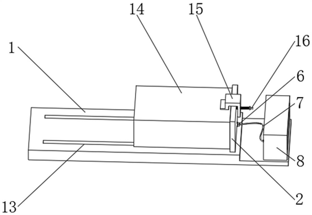
[0036] see figure 2 with Figure 4 As shown in Comparative Example 1, as another embodiment of the present invention, the sliding groove 13 is opened on the top of the bottom plate 1, and the inner side of the sliding groove 13 is provided with a sleeve 14, and the top of the sleeve 14 is provided with a connecting frame 15 , and a threaded rod 16 runs through the inner side of the connecting frame 15 .
[0037] There is a sliding connection between the sleeve box 14 and the sliding groove 13, and there are two sliding grooves 13 arranged symmetrically with respect to the top of the bottom plate 1; the user can effectively adjust the activity of the sleeve box 14 through the setting of the sliding groove 13, and can The setting of the connecting frame 15 rotates the threaded rod 16, so that the sleeve box 14 is close to the vertical plate 2, which is convenient for the user to operate and use the device.
[0038] The connecting frame 15 and the sleeve box 14 are snap-connec...
PUM
 Abstract
Description
Claims
Application Information
 - R&D
- Intellectual Property
- Life Sciences
- Materials
- Tech Scout
- Unparalleled Data Quality
- Higher Quality Content
- 60% Fewer Hallucinations
Browse by: Latest US Patents, China's latest patents, Technical Efficacy Thesaurus, Application Domain, Technology Topic, Popular Technical Reports.
© 2025 PatSnap. All rights reserved.Legal|Privacy policy|Modern Slavery Act Transparency Statement|Sitemap|About US| Contact US: help@patsnap.com


