
Portable fault diagnosis device for electrical system detection

A technology of fault diagnosis device and electrical system, which is applied to the parts of electrical measuring instruments, measuring devices, casings of measuring devices, etc. Practical performance, high safety performance, good loading operation effect

Inactive Publication Date: 2020-11-03
CHONGQING TECH & BUSINESS UNIV
View PDF0 Cites 0 Cited by
  • Summary
  • Abstract
  • Description
  • Claims
  • Application Information

AI Technical Summary

Problems solved by technology

[0004] The purpose of the present invention is to provide a portable fault diagnosis device for electrical system detection, to solve the problem that the existing fault diagnosis device proposed in the background technology is not equipped with a good external extension structure, which makes it difficult to carry out external inspection of the main body. development, which leads to poor practical performance and control performance, which is not conducive to the user's manipulation and use, and because the structural design of its end is not reasonable enough, if it cannot be carried out well, it will cause the device body to be damaged. It is difficult to assemble with foreign objects, etc., and there are cases where the practical performance is extremely poor

Method used


Image

  • Portable fault diagnosis device for electrical system detection
  • Portable fault diagnosis device for electrical system detection
  • Portable fault diagnosis device for electrical system detection

Examples


Embodiment Construction

[0026] The following will clearly and completely describe the technical solutions in the embodiments of the present invention with reference to the accompanying drawings in the embodiments of the present invention. Obviously, the described embodiments are only some, not all, embodiments of the present invention.

[0027] In the description of the present invention, unless otherwise stated, the meaning of "plurality" is two or more; the terms "upper", "lower", "left", "right", "inner", "outer" , "front end", "rear end", "head", "tail", etc. indicate the orientation or positional relationship based on the orientation or positional relationship shown in the drawings, and are only for the convenience of describing the present invention and simplifying the description, rather than Indicates or implies that the device or element referred to must have a particular orientation, be constructed and operate in a particular orientation, and therefore should not be construed as limiting the...


PUM


Abstract

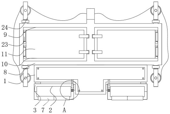
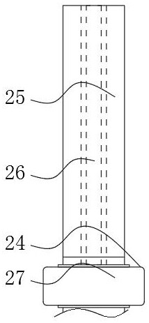
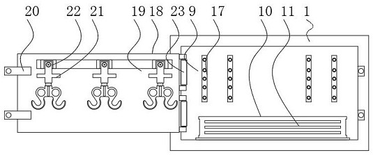
The invention relates to a portable fault diagnosis device for electrical system detection, and the device comprises an end seat and a middle seat, the bottoms of the left and right ends of the end seat are respectively provided with a supporting mechanism, the middle seat is disposed at the top end of the middle part of the end seat, and the interior of the middle seat is provided with an inner chamber. According to the portable fault diagnosis device for electrical system detection, the inner penetrating rod can be rotationally adjusted through the outer rotating base, then the top end of the outer rotating base is linked for adjustment, and the top and the bottom of the outer rotating base are movably connected, so that the outer rotating base can be conveniently adjusted for flexible use; the electric wire can be carried through the transmission wheel at the end part of the outer rotating seat, the bunching operation can be conveniently and well carried out, an extremely high flexible effect is achieved, and meanwhile, each electric appliance assembly can be arranged through the inner chamber, so that measurement articles such as an oscilloscope or a voltmeter can be conveniently carried, and the fault part of an electric system can be conveniently detected; and extremely high convenience is achieved.

Description

technical field [0001] The invention relates to the technical field of electrical system detection, in particular to a portable fault diagnosis device for electrical system detection. Background technique [0002] The electrical system is a system composed of low-voltage power supply components, also known as "low-voltage power distribution system" or "low-voltage power distribution line". Diagnostic maintenance. [0003] Because the existing fault diagnosis device is not equipped with a good extension structure, it is difficult to extend the main body, which leads to its poor practical performance and control performance, which is not conducive to the user's manipulation and use, and because of its terminal The structural design of the part is not reasonable enough, such as the inability to carry out the loading and assembly operation well, which makes it difficult to assemble the device body with foreign objects, etc., and there is a situation of extremely poor practical ...

Claims


Application Information

Patent Timeline
Patent Type & Authority Applications(China)
IPC IPC(8): G01R1/02G01R1/04G01R31/00
CPCG01R1/02G01R1/04G01R31/00
Inventor 喻其炳王芳杨艺
Owner CHONGQING TECH & BUSINESS UNIV
Learn More