Cushioning structure for floor and ground surfaces

a technology for floor and ground surfaces and joints, applied in the direction of ground pavings, traffic signals, roads, etc., can solve the problems of insufficient cushioning, rubber or rubber particles, and the cost of manufacturing and adhesion of two layers of materials, so as to achieve greater cushioning ability, less labor, and less risk.

Inactive Publication Date: 2006-04-25
SKYDEX TECH INC
View PDF3 Cites 61 Cited by
  • Summary
  • Abstract
  • Description
  • Claims
  • Application Information

AI Technical Summary

Benefits of technology

[0020]One advantage of the present invention is that the top surface spreads the impact or load over a large cross sectional area of the cushioning layer. Another advantage of the present invention is that cushioning tiles may be manufactured and shipped at one location, and then installed at the desired site. Another advantage of the present invention is that the installation of the cushioning tiles requires far less labor than the prior art rubber or rubber particle cushioning structures. Another advantage of the present invention is that tiles having varied properties can be connected together at the installation site to accommodate different cushioning needs. For example, tiles having greater cushioning ability can be installed at equipment locations where risks are higher, while tiles having less impact protection can be installed in other lower risk areas.
is that the top surface spreads the impact or load over a large cross sectional area of the cushioning layer. Another advantage of the present invention is that cushioning tiles may be manufactured and shipped at one location, and then installed at the desired site. Another advantage of the present invention is that the installation of the cushioning tiles requires far less labor than the prior art rubber or rubber particle cushioning structures. Another advantage of the present invention is that tiles having varied properties can be connected together at the installation site to accommodate different cushioning needs. For example, tiles having greater cushioning ability can be installed at equipment locations where risks are higher, while tiles having less impact protection can be installed in other lower risk areas.

Problems solved by technology

The first disadvantage relates to the cost of manufacturing and adhering two layers of material together.
A second disadvantage with prior art cushioned surfaces made from rubber or rubber particles is that they do not adequately cushion a fall.
This is because the prior art cushioned structures made from rubber or rubber particles do not provide adequate impact management over the range of force exerted on the surface.
For example, the impact absorption is not predictable throughout the surface and, especially at high impacts, the structures fail to provide sufficient cushioning.
A third disadvantage of prior art cushioning structures made from rubber or rubber particles is their lack of durability.
In the past, many of these materials, such as foam rubber, used for the bottom layer of a two-layer cushioning structure lost their cushioning ability quickly and, failed to provide adequate cushioning for a sufficiently long period of time.
Wearcourse outdoor surfaces have additional disadvantages, primarily related to installation and durability.
For example, wearcourse installation is tedious, labor intensive, and fraught with human error.
Additionally, the range of colors available and customization is very limited.
Lateral shock dispersion, which can reduce or prevent minor injuries such as broken fingers or skin abrasion, also is severely lacking.
Although wood chips or sand are low cost alternatives, they also have disadvantages.
One problem is that they do not provide uniformly adequate depth to provide adequate cushioning.
Wood chips or sand fail to provide adequate cushioning for impacts where the loose fill particles do not have sufficient depth.
A second disadvantage with the loose fill materials is that the surface may not be solid enough to permit wheel chair access, especially where the loose fill material has substantial depth.
Therefore, the use of wood chips or sand in outdoor recreational facilities may present a problem in satisfying the Americans with Disabilities Act access standards.
Mechanical cushioning structures in the prior art also have disadvantages.
Although they may provide acceptable cushioning at low impacts, their cushioning ability is reduced at higher and more dangerous higher impacts.
That is due to the tendency of prior art structure to buckle at high levels of impact.
Specifically, we have found that prior art I-beam cushioning structures tend to buckle at a high level of impact, rendering this cushioning structure ineffective at some point during the impact.

Method used


Image

  • Cushioning structure for floor and ground surfaces
  • Cushioning structure for floor and ground surfaces
  • Cushioning structure for floor and ground surfaces

Examples


first embodiment

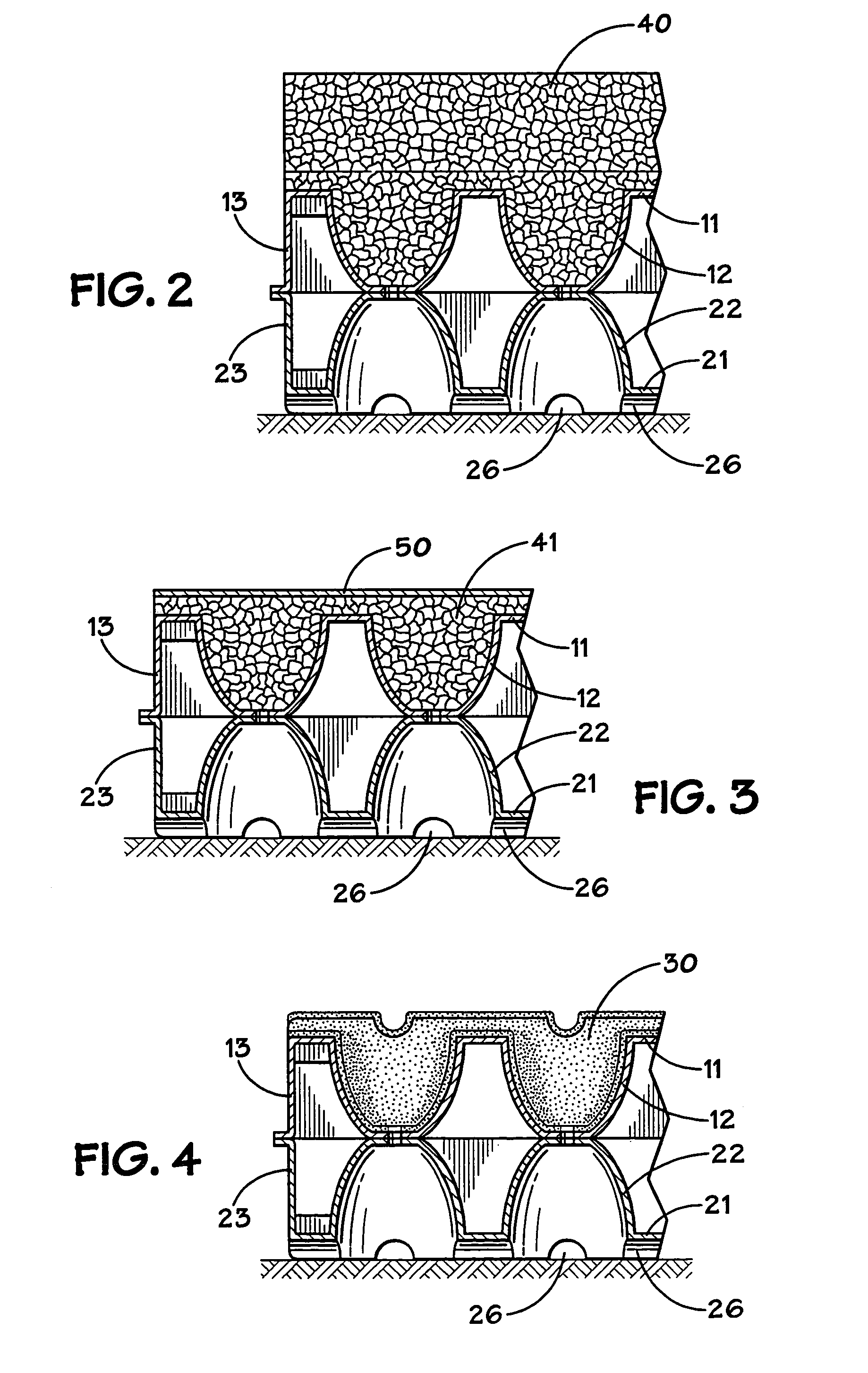
[0031]FIG. 2 shows a first preferred embodiment of the present invention. In the first embodiment, the wearcourse layer consists of rubber particles 40 applied to the outer surface of sheet 11. The rubber particles may partially or completely fill indentations 12. The rubber particles in each indentations may be loose or may be adhered together with a binder such as a urethane binder. The rubber particles may have irregular dimensions or may be spherical or some other shape if desired. Preferably, the rubber particles are elastic and each will have outward dimensions of less than 0.25 inches. Use of rubber granules to partially or completely fill some or all of the indentations helps make the cushioning structure of the invention effective and consistent across the typical temperature range for the outdoor activities.

third embodiment

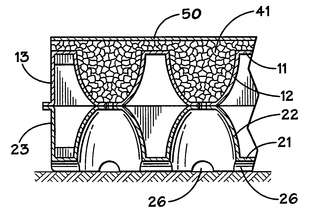
[0032]FIG. 3 shows a second preferred embodiment of the present invention. In the third embodiment, the wearcourse layer consists of moderator 50, which is a sheet of plastic or rubber material applied to the outwardly facing surface of sheet 11. The moderator may be adhered to sheet 11 with adhesive or spot welded to the outer surface of sheet 11. As shown in FIG. 3, moderator 50 may cover a layer of rubber particles 41 that partially or completely fill indentations 12. Alternatively, the moderator and sheet each may have mating protrusions and holes to fit over the protrusions, so that the moderator is engaged to the sheet. Optionally, the moderator may have additional cushioning members with a regular grid or pattern, and hemispherical protrusions that extend into indentations. The protrusions may be integral to the moderator. Optionally, fiber particles also may be applied to the outer surface of the moderator.

[0033]FIG. 4 shows a third preferred embodiment of the present invent...


PUM

PropertyMeasurementUnit
thicknessaaaaaaaaaa
thicknessaaaaaaaaaa
thicknessaaaaaaaaaa

Abstract

A flexible shock absorbing component providing cushioning for surfaces, especially wall and floor surfaces, is described. The shock absorbing component includes two sheets of thermoplastic, each sheet with inwardly facing, opposing, resiliently compressible indentations extending into a cavity between the two sheets. The shock absorbing component also includes a layer of particulate matter applied to and adhered to the outer surface of one of the sheets, to provide wear and weather resistance. A moderator may also be attached to the outer surface of the sheet.

Description

[0001]The present application is a continuation application of, and claims priority to, U.S. application Ser. No. 09 / 976,262, filed Oct. 12, 2001 now U.S. Pat. No. 6,777,062, which in turn claimed priority to U.S. Provisional Patent Application Ser. No. 60 / 240,006, filed Oct. 12, 2000. The entirety of these prior disclosures are incorporated by reference herein without discretion.BACKGROUND OF THE INVENTION[0002]1. Field of the Invention[0003]The present invention relates to shock absorbing components and to methods of manufacturing shock absorbing components. More particularly, the invention relates to flexible shock absorbing components used to provide cushioned surfaces or surface coverings.[0004]2. Description of Related Art[0005]There are many cushioning surfaces that have been used for athletic and recreational activities in indoor as well as outdoor facilities. For example, cushioned surfaces have been used for floor coverings or wall surfaces in indoor gymnasiums for indoor ...

Claims


Application Information

Patent Timeline
Patent Type & Authority Patents(United States)
IPC IPC(8): B32B3/20E04F15/22B32B3/26D06N7/04E01C13/04E01C13/06F16F1/376F16F3/093
CPCB32B3/26E01C13/065E04F15/225F16F1/376F16F3/093F16F3/0935E01C13/045Y10T428/24372E01C2201/205E01C2201/207Y10T428/24661Y10T428/24562Y10T428/24554Y10T428/24678Y10T428/234Y10T428/16Y10T428/24628Y10T428/24405
Inventor SKAJA, JOSEPH J.
Owner SKYDEX TECH INC
Why Eureka
Try Eureka