Robot system

A robot system and robot technology, applied in the field of robot systems, can solve problems such as the increase in the number of drive parts and the decrease in the load-bearing capacity of the end effector

Active Publication Date: 2020-09-04
SEIKO EPSON CORP
View PDF8 Cites 2 Cited by
  • Summary
  • Abstract
  • Description
  • Claims
  • Application Information

AI Technical Summary

Problems solved by technology

[0004] However, in the above-mentioned configuration, the number of drive units increases in accordance with the increa...

Method used


Image

  • Robot system
  • Robot system
  • Robot system

Examples


no. 1 approach

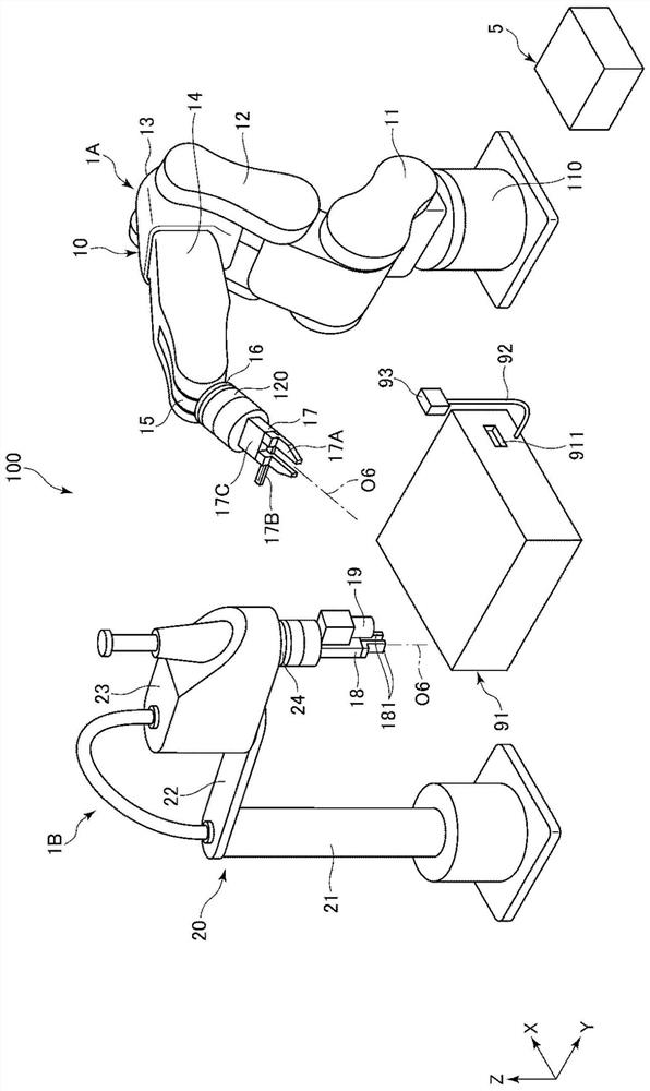
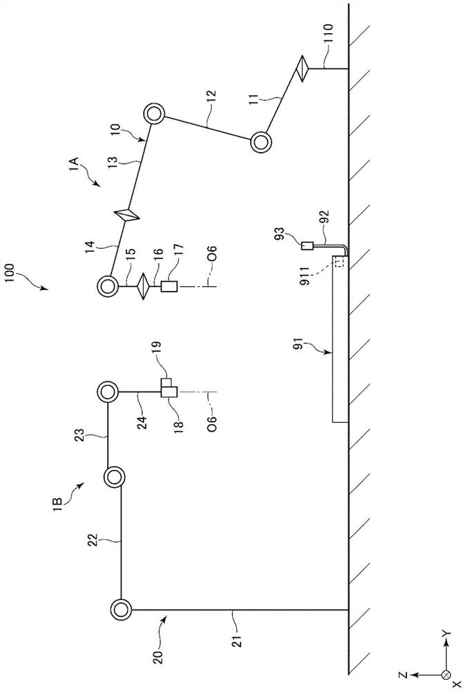
[0038] exist figure 1 In the diagram, three axes (X axis, Y axis, and Z axis) orthogonal to each other are shown in the figure. In addition, below, the direction parallel to the X-axis is also referred to as the "X-axis direction", the direction parallel to the Y-axis is also referred to as the "Y-axis direction", and the direction parallel to the Z-axis is also referred to as the "Z-axis direction". . In addition, below, the front-end|tip side of each illustrated arrow is called "+ (positive)", and the proximal side is called "- (negative)". In addition, the Z-axis direction corresponds to the "vertical direction", and the direction parallel to the X-Y plane corresponds to the "horizontal direction". In addition, the + (positive) side of the Z axis is referred to as "upper", and the - (negative) side of the Z axis is referred to as "lower". It should be noted that in figure 2 The illustration of the force detection unit 120 is omitted.

[0039] robot system

[0040] f...

Deformed example 1

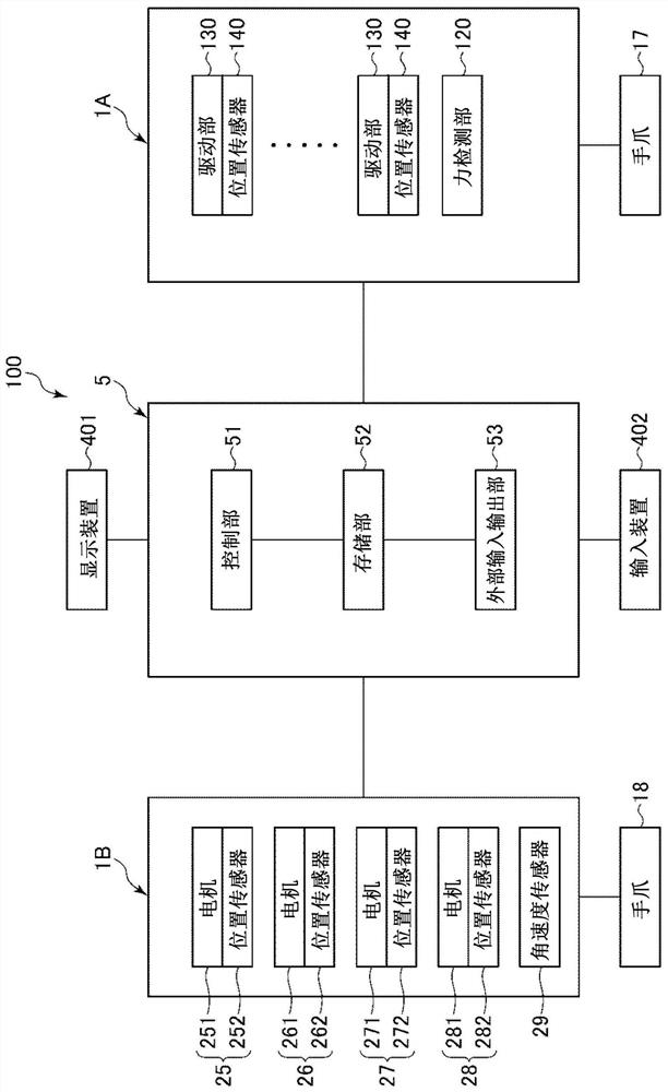
[0161] Figure 26 It is a block diagram showing Modification 1 centering on the hardware of the robot system.

[0162] Figure 26 The overall structure of the robot system 100B in which the computer 63 is directly connected to the robot 1A and the robot 1B is shown in . The control of the robot 1A and the robot 1B is directly executed by the processor existing in the computer 63 reading the instructions in the memory.

[0163] Therefore, the computer 63 can be regarded as a "control device".

Deformed example 2

[0165] Figure 27 It is a block diagram showing Modification 2 centering on the hardware of the robot system.

[0166] Figure 27 The figure shows the overall configuration of a robot system 100C in which the robot 1A and the robot 1B incorporating the controller 61 are connected to a computer 66 , and the computer 66 is connected to a cloud 64 via a network 65 such as a LAN. The control of the robot 1A and the robot 1B may be executed by a processor existing in the computer 66 reading instructions in the memory, or may be executed by a processor existing in the cloud 64 reading instructions in the memory via the computer 66 .

[0167] Therefore, any one of the controller 61, the computer 66, and the cloud 64, or any two or three of them can be regarded as a "control device".


PUM


Abstract

The invention provides a robot system capable of sufficiently ensuring load-bearing capacity. The robot system is characterized by being provided with: a robot having an arm; and a gripper connected to the arm, the gripper having: a first grip section having a first claw part and a second claw part that approach or separate from each other; a second holding part having a third claw part and a fourth claw part which are close to or separated from each other; and a drive unit for driving the first holding part and the second holding part, wherein the first claw part is connected to the third claw part, the third claw part is separated from the fourth claw part when the drive unit brings the first claw part and the second claw part closer to each other, and the third claw part is brought close to the fourth claw part when the drive unit separates the first claw part and the second claw part.

Description

technical field [0001] The present invention relates to robotic systems. Background technique [0002] For example, Patent Document 1 discloses a robot system including an articulated robot and a controller for controlling the articulated robot. The articulated robot described in Patent Document 1 includes a robot arm and an end effector attached to the tip of the robot arm. In addition, the end effector of Patent Document 1 has two operation parts, and since each operation part can perform different types of operations, replacement of the end effector for each operation can be omitted. [0003] Patent Document 1: Japanese Patent Laid-Open No. 2015-003374 [0004] However, in the configuration as described above, the number of driving units increases in accordance with the increase in the number of working units. Therefore, the weight of the end effector increases resulting in a decrease in the load-bearing capacity. Contents of the invention [0005] The present inven...

Claims


Application Information

Patent Timeline
IPC IPC(8): B25J9/16B25J13/08B25J15/08
CPCB25J9/1602B25J13/086B25J13/088B25J15/08
Inventor 桝川友靖宫本义人上田淳也八寻勇树小岛嗣也
Owner SEIKO EPSON CORP
Why Eureka
Try Eureka