Method, device, terminal and storage medium for determining discharge threshold of energy storage device

A discharge threshold and energy storage device technology, applied in the direction of circuit devices, AC network circuits, AC network load balancing, etc., can solve the problem of optimal capacity configuration design of energy storage devices, inability to guarantee peak shaving effect, and lack of methods for determining discharge thresholds And other issues

Active Publication Date: 2021-03-02
DUNSHI MAGNETIC ENERGY TECH
View PDF3 Cites 0 Cited by
  • Summary
  • Abstract
  • Description
  • Claims
  • Application Information

AI Technical Summary

Problems solved by technology

[0005] In view of this, the embodiments of the present invention provide a method, device, terminal and storage medium for determining the discharge threshold of an energy storage device, so as to solve the problem that the existing energy storage device lacks a method for determining the discharge threshold, and cannot guarantee the effect of peak clipping and energy storage. The design of device capacity configuration achieves the optimal problem

Method used


Image

  • Method, device, terminal and storage medium for determining discharge threshold of energy storage device
  • Method, device, terminal and storage medium for determining discharge threshold of energy storage device
  • Method, device, terminal and storage medium for determining discharge threshold of energy storage device

Examples


Embodiment Construction

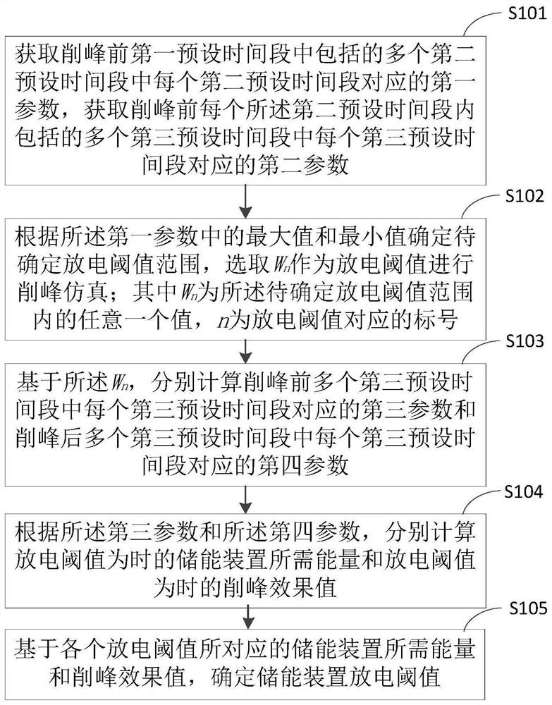
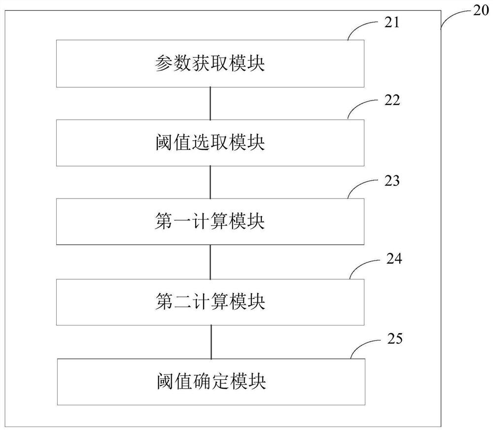
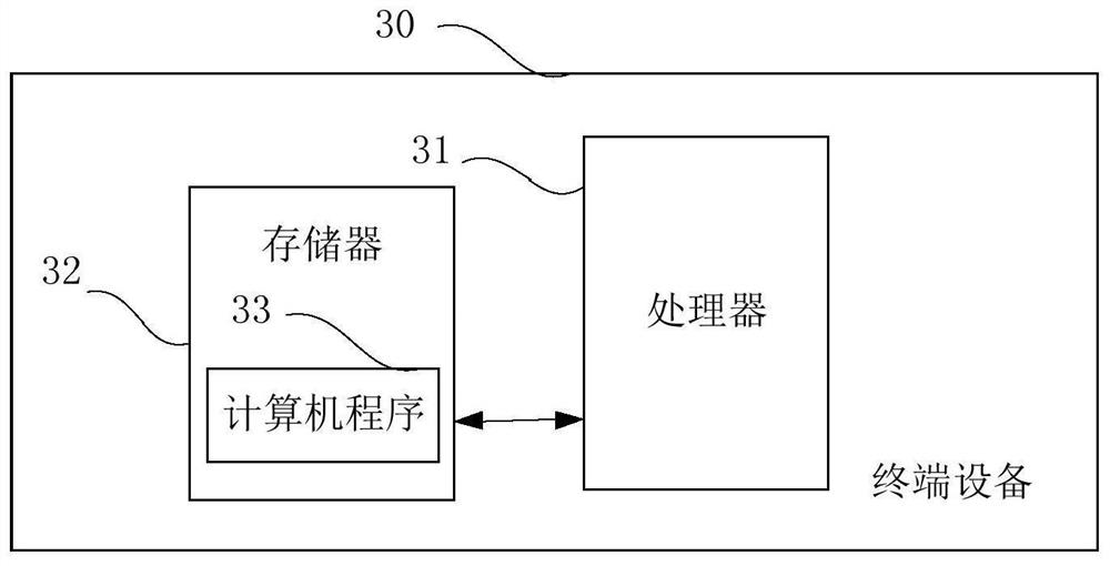
[0045] In the following description, specific details such as specific system structures and technologies are presented for the purpose of illustration rather than limitation, so as to thoroughly understand the embodiments of the present invention. It will be apparent, however, to one skilled in the art that the invention may be practiced in other embodiments without these specific details. In other instances, detailed descriptions of well-known systems, devices, circuits, and methods are omitted so as not to obscure the description of the present invention with unnecessary detail.

[0046] The term "comprising" and any other variants in the specification and claims of the present invention and the above drawings mean "including but not limited to", and are intended to cover non-exclusive inclusion. For example, a process, method or system, product or device comprising a series of steps or units is not limited to the listed steps or units, but optionally also includes steps or...


PUM


Abstract

The invention is applicable to the technical field of electrified railways, in particular relates to a method and device for determining a discharge threshold of an energy storage device, a terminal and a storage medium. The method comprises the steps of obtaining a first parameter corresponding to each of second preset time periods included in a first preset time period before peak clipping, andobtaining a second parameter corresponding to each of third preset time periods included in each second preset time period before peak clipping; determining a to-be-determined discharge threshold range according to the maximum value and the minimum value in the first parameter, and selecting Wn as a discharge threshold to perform peak clipping simulation; calculating the energy required by the energy storage device when the discharge threshold is Wn and the peak clipping effect value when the discharge threshold is Wn; and determining the discharge threshold of the energy storage device basedon the energy required by the energy storage device corresponding to each discharge threshold and the peak clipping effect value. The discharge threshold determined by the method can ensure that the peak clipping effect and the comprehensive effect of capacity configuration of the energy storage device are optimal.

Description

technical field [0001] The invention belongs to the technical field of electrified railways, and in particular relates to a method, device, terminal and storage medium for determining a discharge threshold of an energy storage device. Background technique [0002] Electrified railway has the development characteristics of high speed and heavy load, and its traction load has large power and large fluctuation. The design of traction transformers needs to meet the demand of load peak power, which leads to large redundancy of transformer installation capacity, low utilization rate and high transformer price. AC drive trains generate a large amount of braking energy during braking, which is directly sent back to the power system. The power department adopts the charging method of "reverse sending and positive calculation" for the returning braking energy, which is not conducive to the efficient and economical operation of the railway department, resulting in regenerative systems....

Claims


Application Information

Patent Timeline
Patent Type & Authority Patents(China)
IPC IPC(8): H02J3/28
CPCH02J3/28H02J2203/20
Inventor 李玉光王大杰王存岗陈鹰唐英伟李胜飞李彦吉苏伟伟
Owner DUNSHI MAGNETIC ENERGY TECH
Why Eureka
Try Eureka