Adjustable cloth chair wood leg cutting device

A cutting device and adjustable technology, applied in feeding devices, sawing components, sawing equipment, etc., can solve the problems of labor-intensive, easy to cause safety accidents, dangers, etc., and achieve simple operation, ensure safety, and save labor. Effect

Inactive Publication Date: 2020-09-08
王封山
View PDF6 Cites 2 Cited by
  • Summary
  • Abstract
  • Description
  • Claims
  • Application Information

AI Technical Summary

Problems solved by technology

[0003] At present, the method of cutting logs into wooden legs is usually to manually place the logs on the cutting device, and then pull the logs to move back and forth on the cutting device and cut through the cutting device. The above-mentioned method has certain dangers during operation. , it is easy to cause safety accidents, and it is more manpower-intensive during operation

Method used


Image

  • Adjustable cloth chair wood leg cutting device
  • Adjustable cloth chair wood leg cutting device
  • Adjustable cloth chair wood leg cutting device

Examples


Embodiment 1

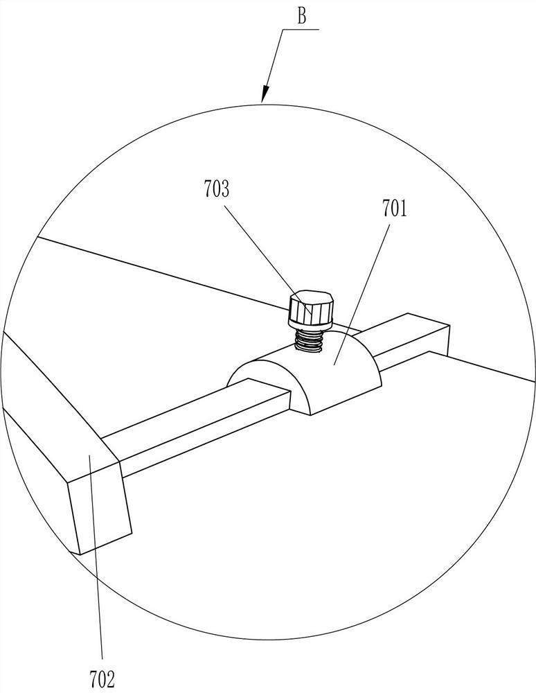
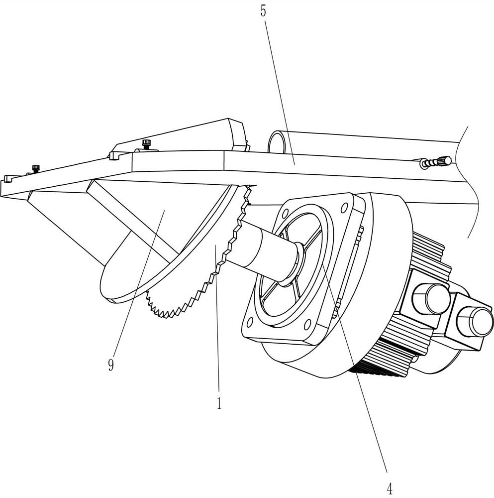
[0026] An adjustable fabric stool wooden leg cutting device such as Figure 1-5 As shown, it includes base plate 1, supporting leg 2, fixed snap ring 3, motor 4 and saw blade 5, supporting legs 2 are connected to the left and right sides of the bottom of base plate 1, and fixed snap ring 3 is connected to the middle of the bottom of base plate 1. A motor 4 is installed on the ring 3, a saw blade 5 is connected to the output shaft of the motor 4, a blanking opening is opened on the rear side of the top of the bottom plate 1, the upper part of the saw blade 5 passes through the blanking opening, and a transmission device 6 and a limiter are also included. Device 7, the top of the bottom plate 1 is provided with a limit device 7 and a transmission device 6.

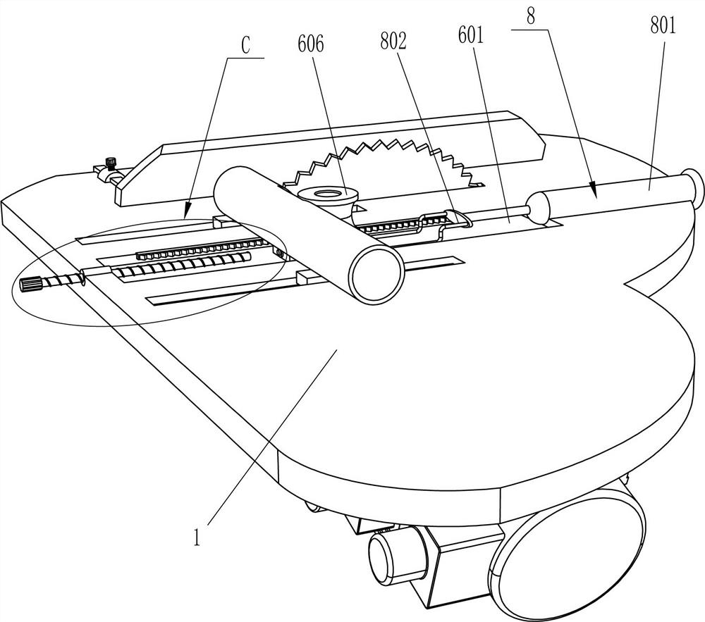
[0027] The transmission device 6 includes a fixed pipe 603, a connecting plate 604, a one-way gear 605, a transmission roller 606, and a rack 607. There is a chute 601 in the middle of the top of the base plate 1, and mounti...

Embodiment 2

[0031] On the basis of Example 1, such as Figure 4-5 As shown, drive device 8 is also included, and drive device 8 includes cylinder 801, connecting rod 802, threaded sleeve 803, second screw rod 804 and reset switch 805, and base plate 1 top right side is equipped with cylinder 801, and the telescoping rod of cylinder 801 A connecting rod 802 is connected to the top, and the connecting rod 802 is connected to the connecting plate 604. A threaded sleeve 803 is connected to the left side of the top of the bottom plate 1, and a second screw 804 is threaded in the threaded sleeve 803, and the second screw 804 is located on the left side of the connecting plate 604. , the left side of the connecting plate 604 is connected with a reset switch 805 , the reset switch 805 is electrically connected with the cylinder 801 , and the reset switch 805 is in contact with the second screw rod 804 .

[0032] Initially, the telescopic rod of the cylinder 801 is in a slightly extended state. Wh...


PUM


Abstract

The invention relates to a cutting device, in particular to an adjustable cloth chair wood leg cutting device. The technical problem to be solved is how to design an adjustable cloth chair wood leg cutting device capable of guaranteeing use safety of operators during operation and capable of saving manpower. The adjustable cloth chair wood leg cutting device comprises a bottom plate, a motor, a transmission device and a limiting device. The two sides of the bottom of the bottom plate are connected with landing legs, and a fixed clamp ring is connected to the middle of the bottom of the bottomplate. The motor is mounted on the fixed clamp ring, a saw blade is connected to an output shaft of the motor, a material falling opening is formed on the rear side of the top of the bottom plate, andthe upper portion of the saw blade penetrates through the material falling opening. The transmission device is arranged at the top of the bottom plate. The limiting device is arranged at the top of the bottom plate. According to the adjustable cloth chair wood leg cutting device, logs are cut into wood legs through cooperative running of the saw blade and the transmission device, and therefore the effect of cutting wood legs is achieved.

Description

technical field [0001] The invention relates to a cutting device, in particular to an adjustable cutting device for wooden legs of a fabric stool. Background technique [0002] Among the seats, the furniture stool, the Mazar is the first to appear. It is the predecessor of the stool. Adding a backrest to the stool has evolved into a chair. The title of stool in the folk is called 杌stool. It was originally used to step on horses and sedan chairs, so it is also called horse stool and sedan chair stool. In modern society, fabric stools are also made for more convenient use. When the fabric stools are made, the four wooden legs on it all need to be cut off from the log, and then the cut wooden legs are installed on the fabric stools. [0003] At present, the method of cutting logs into wooden legs is usually to manually place the logs on the cutting device, and then pull the logs to move back and forth on the cutting device and cut through the cutting device. The above-mention...

Claims


Application Information

Patent Timeline
Patent Type & Authority Applications(China)
IPC IPC(8): B27B5/22B27B5/29B27B31/00
CPCB27B5/222B27B5/29B27B31/003
Inventor 王封山
Owner 王封山
Why Eureka
Try Eureka