Industrial automatic dicing device for plywood

A technology for plywood and industrial use, which is applied in the field of automatic cutting device for industrial plywood, which can solve the problems of low cutting quality, incomplete cutting surface, inconvenient operation, etc., and achieve the effect of cutting materials

Active Publication Date: 2021-05-04
临沂汇丰木业有限公司
View PDF13 Cites 2 Cited by
  • Summary
  • Abstract
  • Description
  • Claims
  • Application Information

AI Technical Summary

Problems solved by technology

[0005] In order to overcome the disadvantages of inconvenient cutting operation, incomplete cutting surface and low cutting quality of traditional plywood, the technical problem of the present invention is to provide an automatic cutting device for industrial plywood with convenient operation, complete cutting surface and high cutting quality

Method used


Image

  • Industrial automatic dicing device for plywood
  • Industrial automatic dicing device for plywood
  • Industrial automatic dicing device for plywood

Examples


Embodiment 1

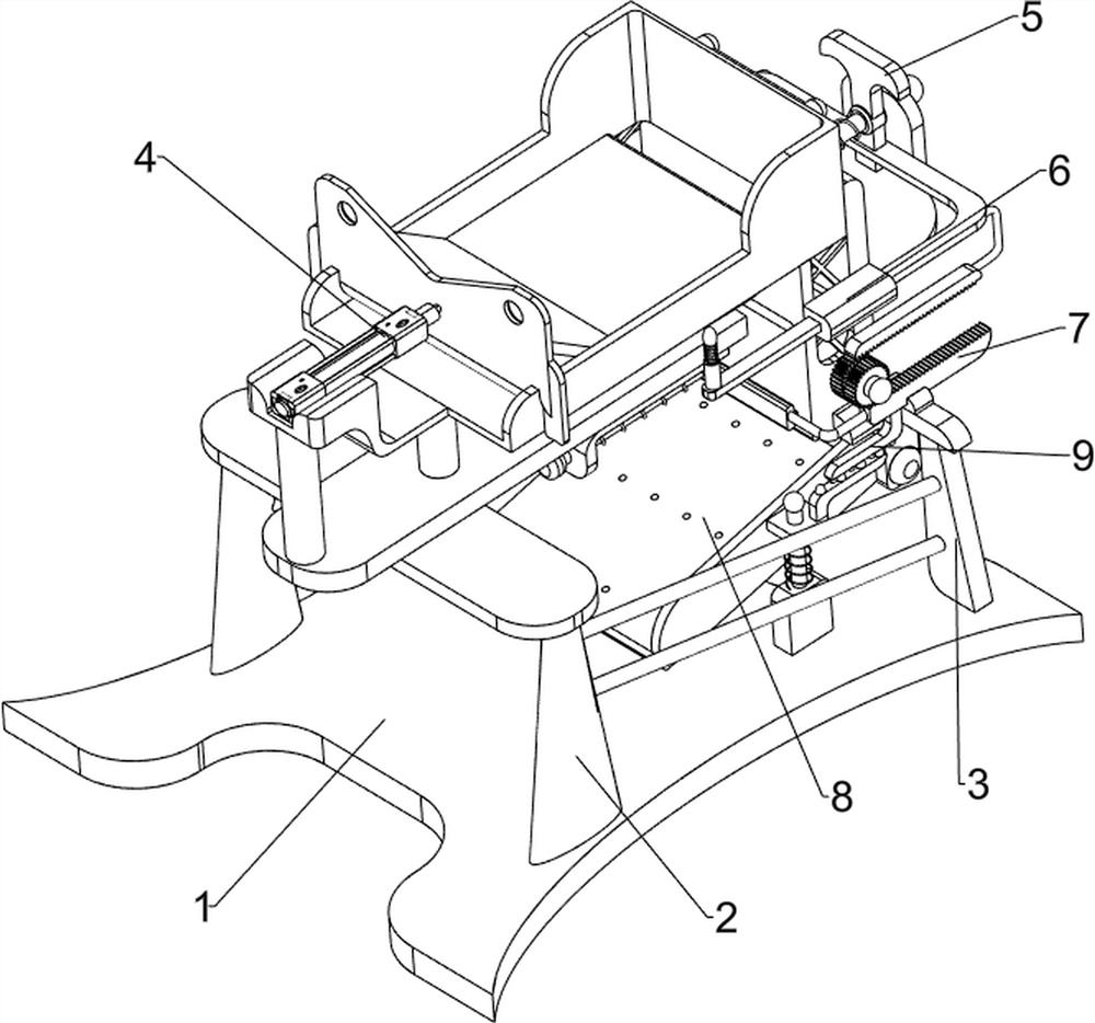
[0066] A kind of industrial three-ply board automatic cutting device, such as figure 1As shown, it includes a base 1, a support frame 2, a first fixed frame 3, a pushing mechanism 4 and a cutting mechanism 5, a support frame 2 is provided on the front side of the base 1, and a first The fixing frame 3, the first fixing frame 3 is connected with the supporting frame 2, the pushing mechanism 4 is arranged on the top of the supporting frame 2, and the cutting mechanism 5 is arranged between the two first fixing frames 3.

[0067] When people want to cut plywood into pieces, this industrial plywood automatic cutting device can be used. First, the user places the plywood in the pushing mechanism 4, starts the pushing mechanism 4, and the pushing mechanism 4 pushes the plywood into the cutting mechanism 5. The cutting mechanism 5 is driven by the pushing mechanism 4 to run, and the cutting mechanism 5 cuts the plywood into pieces. After the cutting of the plywood is completed, the p...

Embodiment 2

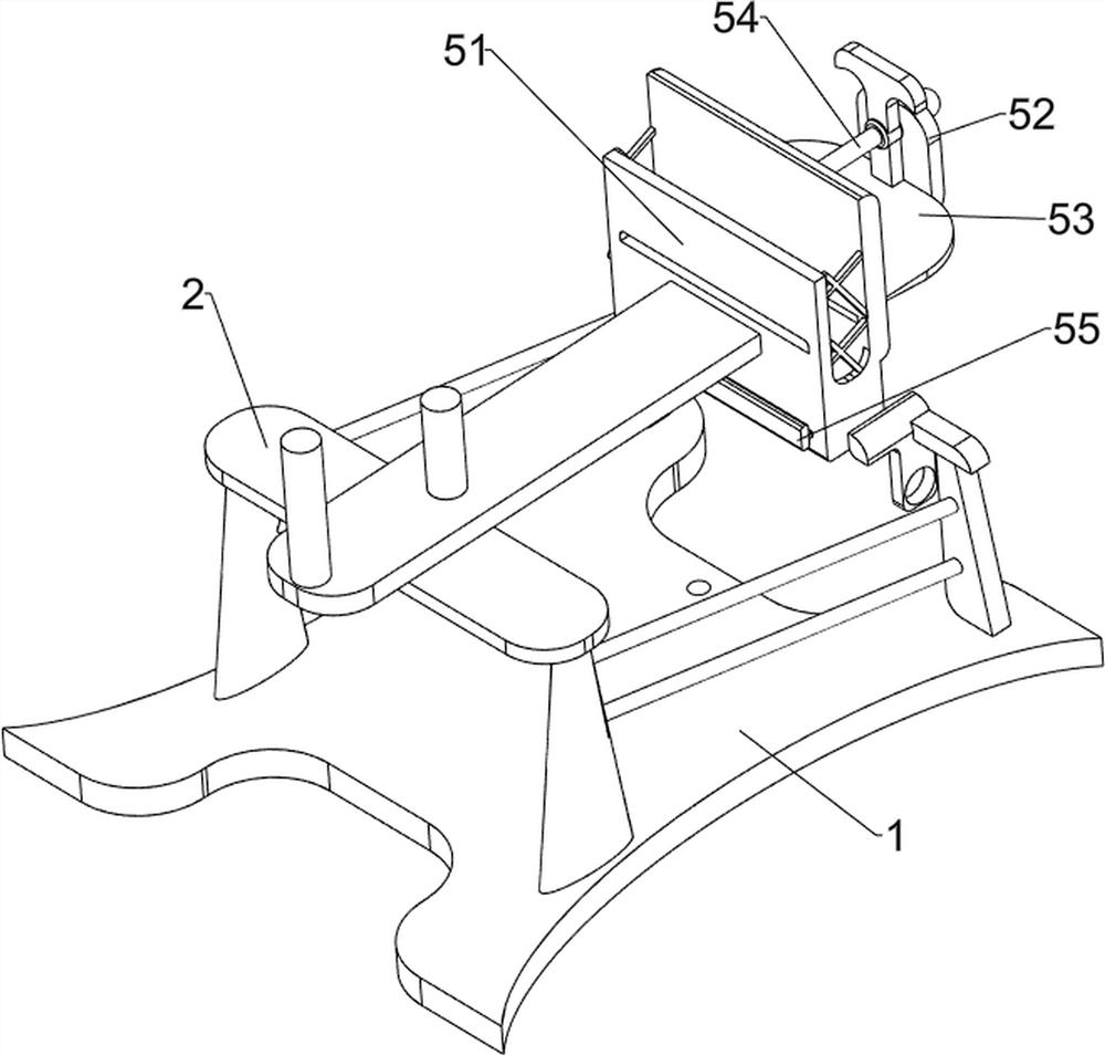
[0069] On the basis of Example 1, such as figure 2 and image 3 As shown, the pushing mechanism 4 includes a first fixed block 41, a cylinder 42, a stand 43 and a first push frame 44, the top of the support frame 2 is provided with a first fixed block 41, and the top of the first fixed block 41 is equipped with a cylinder 42, Support frame 2 rear side is provided with platform 43, and platform 43 is connected with first fixed block 41, and cylinder 42 telescoping rod is connected with first pushing frame 44, and first pushing frame 44 and platform 43 slide fits.

[0070] The user places the plywood on the stand 43, starts the cylinder 42, the telescopic rod of the cylinder 42 stretches backward, and the telescopic rod of the cylinder 42 drives the first push frame 44 to move backward, and the first push frame 44 pushes the plywood backward to realize Propelling effect, after the three-ply board is pushed, control the telescopic rod of the cylinder 42 to shorten forward, ther...

Embodiment 3

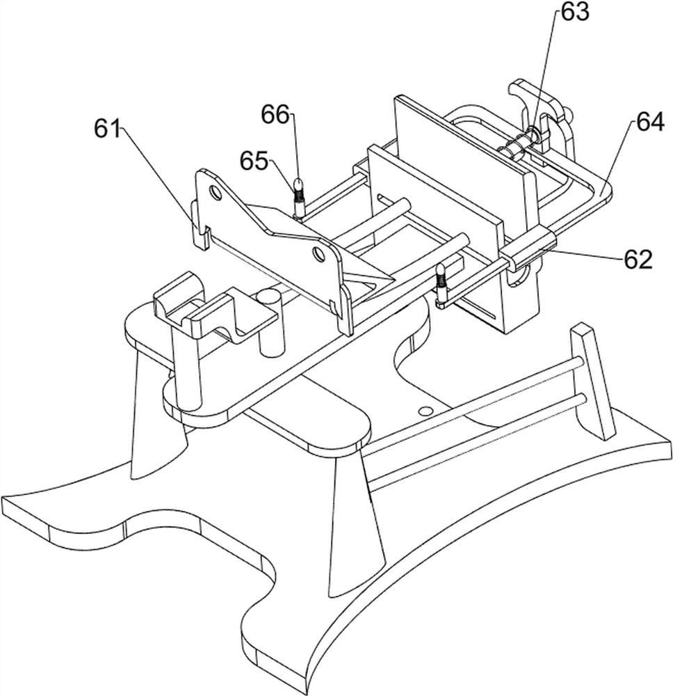
[0074] On the basis of Example 2, such as Figure 4-Figure 7 As shown, a reciprocating mechanism 6 is also included, and the second fixed frame 51 is provided with a reciprocating mechanism 6. The reciprocating mechanism 6 includes a pushing block 61, a second sliding sleeve 62, a third spring 63, a second pushing frame 64, a first The telescopic rod 65 and the touch block 66, the left and right sides of the first push frame 44 are all provided with the push block 61, the left and right sides of the second fixed frame 51 are all provided with the second sliding sleeve 62, and the first sliding rod 54 is wound with the second sliding sleeve. Three springs 63, the two ends of the third spring 63 are respectively connected with the second fixed mount 51 and the cutting blade 53, and the second push frame 64 is slidably connected between the two second sliding sleeves 62, and the second push frame 64 is connected with the cutting blade. 53 connection, the second push frame 64 left...


PUM


Abstract

The invention relates to a dicing device, in particular to an industrial automatic dicing device for plywood, and aims to provide the industrial automatic dicing device which is used for the plywood and is convenient to operate, complete in cutting surface and relatively high in cutting quality. The industrial automatic dicing device for the plywood comprises a base, first fixing frames, a pushing mechanism and a cutting mechanism; a supporting frame is arranged on the base; the two first fixing frames are arranged on one side of the base and are connected with the supporting frame; the pushing mechanism is arranged at the top of the supporting frame; and the cutting mechanism is arranged between the two first fixing frames. An air cylinder telescopic rod extends backwards and drives a first pushing frame to move backwards, the first pushing frame pushes the plywood backwards, and the pushing effect is achieved.

Description

technical field [0001] The invention relates to a cutting device, in particular to an automatic cutting device for industrial plywood. Background technique [0002] Three-plywood is a common plywood, which is made by sticking three layers of veneer together according to different grain directions. Although the existing cutting device can cut three-plywood, but due to the complex structure of the cutting device, it is not easy to maintain when the device fails. , and the plywood is laminated by three layers of thin wood, so when cutting from the surface of the plywood, it is easy to cause the surface of the plywood to be cut unevenly, which not only affects the appearance, but also easily damages the plywood. When the cutting knife becomes dull after long-term use, it is easier Damage the veneer inside the plywood. [0003] Patent application CN207901344U, with a publication date of 20180925, discloses a fixing device for plywood cutting, including a base, a support rod, a m...

Claims


Application Information

Patent Timeline
Patent Type & Authority Applications(China)
IPC IPC(8): B27C5/02
CPCB27C5/02
Inventor 邱灿文
Owner 临沂汇丰木业有限公司
Why Eureka
Try Eureka